Showing posts with label conservation. Show all posts

Sunday, August 8, 2021

On Pendentives

A tale of two domes

Perhaps two of the most important domes from antiquity are those belonging to the Pantheon in Rome and the Hagia Sofia of Istanbul. Although the latter is to be found in modern day Turkey, it is of course from the era of Byzantine rule in Constantinople and is therefore of Roman origin.


From their outward appearance the two domes would appear to be similar, indeed how different can the construction of a dome be? Further inquiry would reveal that the materials used to construct the two domes are different. The Pantheon is made of unreinforced concrete, while the Hagia Sofia’s dome is of masonry. Indeed the Pantheon remains the world’s largest unreinforced concrete dome to this day.


This difference is interesting, but in my view is not fundamental to the way in which these two revolutionary structures work. I am perfectly aware of the Pantheon’s oculus, its coffered soffit, the variation in concrete mix over its height, all of which were designed to save weight. These are important details, which are both interesting and worthy of study, maybe I will write about them in some future point, however they are not directly relevant to the subject of this post.

The first thing to note is that classical domes, like later gothic structures, are what I would describe as gravitational or compressive equilibrium structures. That is to say that their structural adequacy is dependent on their shape and not on materials science. This is possible because actual stresses are compressive and sufficiently low that, providing equilibrium is maintained, material strength is unimportant. This makes sense because materials science, at least in the modern sense of stresses and strains, did not exist when they were built. 

Those familiar with the structures in question will no doubt be aware of known cracking in both domes, which might be taken to suggest that there is in fact some material science going on, however as we shall see this is not the case.

To understand the primary difference between the Pantheon and Hagia Sofia, perhaps it is first necessary to explain how a generic dome works. In section domes behave in a similar manner to arches, because their curved profile exerts both vertical and lateral thrust at the seating[1]. Domes are of course unlike arches in the sense that they are 3D structures. This means that the aforementioned vertical thrusts are expressed as compressive meridional stresses extending from the crown of the dome to it’s base. The lateral thrusts push outwards in all directions generating a circumferential or hoop stress that cause domes to spread. It is the way in which the meridional and circumferential stresses are resisted that makes the difference.

Like barrel vaulted structures from the classical period of history the Pantheon is supported on heavy walls that follow the profile of the roof structure, in this case a cylinder, in order to buttress the roof against spreading. Some descriptions I have read speculate a stepped thickening observed at the dome’s base is designed to provide a circumferential tie. Maybe their authors have done more research than me and have data to support this view, however I am disinclined to adopt it based solely on my own intuition that the tensile capacity of concrete, albeit Roman concrete, is too low. Also, if tension were present it would imply materials science is at work to provide the required equilibrium, which is philosophically less satisfying.

It occurs to me that a more elegant solution, which maintains the idea of gravitational equilibrium, would be one where the purpose of the steps was to increase weight at the head of the supporting wall in order to push the dome’s thrust line back into the supporting walls. In essence it would behave, at least in my estimation, like the pinnacle atop a flying buttress.


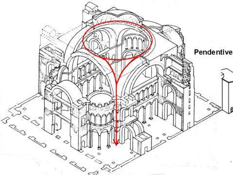
The dome of the Hagia Sofia is different. It does not find support from heavy buttress walls. Rather it straddles the four corners of a vast open space into which light and air may flood. In character it is a medieval structure whose load paths concentrate the dome’s weight into a carefully defined masonry skeleton. The invention that makes this possible are the inverted triangular masonry panels, known as pendentives, that are located over the four supporting piers. As they spread outwards from their apex a series of four arches are formed on the dome’s perimeter. Together these elements funnel load into the supporting piers where the in plane arch thrusts are buttressed.

It is evident however that there remains unbalanced thrusts perpendicular to the apex of each pendentive arch. Equilibrium is restored by hemispherical domes that lean in the opposite direction to the dome’s thrust in one direction and buttresses in the other.


And so it is that the dome at Hagia Sofia represents a transition between heavy buttress walls and gothic cathedrals of the later medieval period, whose structures had a more clearly defined order of primary and secondary elements and a more sophisticated understanding of load paths.

Now, to the aforementioned cracks in both domes. Many seasoned observers hold the view that these are the result of past seismic events and differential settlements. Indeed the original dome at Hagia Sofia is known to have collapsed during an earthquake leading to the present cupola being constructed with a higher profile in order to reduce the magnitude of lateral thrusts. 

Nevertheless it would appear that in spite of movement to both structures gravitational equilibrium has been restored. They remain stable, or at the very least, are moving very slowly.


[1] For further information I have written several prior posts relating to the behaviour arch structures.

Sunday, June 27, 2021

On Lunes & Cracks

Conserving St Peter’s Basilica


The dome of St Peter’s Basilica in Rome is one of the most recognised structures in the world. It was completed around 1590 and was conceived by the genius Michelangelo. There are many reasons why it is special structure, but perhaps the most important is amongst the least well known.

By around 1680 cracks were being reported in the dome, which unsurprisingly caused some to question its safety. Concerns were exacerbated following an earthquake in 1730. Meridional cracking, associated with a dome’s tendency to spread at the base, was well known in the sixteenth century and therefore, following a detailed investigation, a recommendation was made to supplement the existing wrought iron hoops, which were intended to prevent spreading, with three or four more.


It would seem that the Vatican had travelled a distance since Galileo’s heresy trial and the incumbent Pope Benedict XIV, unlike many designers and practitioners of the day, was impressed by the progress made by scientists and mathematicians of the day. He therefore commissioned three of them; Thomas Seur, Francois Jacquier & Roggiero Boscovich to examine the subject. The publication of their findings in 1743 was a seminal moment for Structural Engineering, because they had based their conclusions on a mathematical analysis of the dome. It was the first known occasion when this was done in any meaningful way. Their approach included a model of the dome’s weight, its materials and two different behavioural scenario’s. The method they adopted for combining this information would today be called ‘virtual work’.

They concluded that the existing iron rings embedded within the dome were insufficient to prevent spreading and that the dome would collapse. They therefore proceeded to calculate the number and proportions of additional rings. This was of course a safe recommendation, however it overlooked the rather important fact that the dome had not in fact collapsed and was very much still standing.

Though they were three of the smartest mathematicians of their day they had made the same basic error that almost every graduate engineer makes at some point. They had placed their confidence in their model over what they could see with their eyes. One of the most important truisms of structural engineering is that a structure will remain in place until it has exhausted every possible means of standing. Consequently, if a mathematical model says a structure will collapse, but it stubbornly refuses to do so, then one is obliged to conclude that the model is wrong and not reality.

The presiding committee responsible for the church’s upkeep did what committees often do. They ignored the expert report and continued to monitor the structure. Benedict was also dissatisfied, but wished to persevere with a scientific approach. He commissioned a new study by a different expert Giovanni Poleni. 

Poleni criticised aspects of the first report and tackled the problem with a different approach. While he conceived his own mathematical model, Poleni was also aware of Robert Hooke’s work on the stability of arches, which is described in an earlier post [On Balloons, Chains and Arches]. He therefore imagined the dome to be split into a series of lunes each of which rested against an opposing lune on the other side of the dome. He then used a physical model to demonstrate that the line of thrust for a pair of lunes lay within the depth of their cross section and would therefore meet Hooke’s criteria for a stable arch. By this reasoning the whole dome, being a series of balanced lunes, would be stable in spite of its meridional cracks.

Nevertheless, Poleni also recommended four additional wrought iron hoops, which were installed in 1744. A further hoop was added in 1747, when it was discovered that one of the originals had in fact fractured.

While the application of mathematics to structural engineering problems, which was pioneered by Seur, Jacquier and Roggiero, would prove successful in the long run it is not difficult to see why it was unsuccessful to begin with. 

While mathematicians and scientists had been publishing treatise on engineering subjects from the early eighteenth century, architects and engineers of the day were unacquainted with mathematical argument and treatise were therefore largely ignored.

A second, and perhaps more significant issue, was the relative maturity of the respective disciplines. Eighteenth century mathematical models, though brilliant in their conception, were no match for 1,000 years of engineering experience, which had refined and optimised known structural forms about as much as it was possible. The only conceivable  advantage for science would be for the conception of structures for which there was no precedent.

This dichotomy caused a divergence in engineering practise between Britain and its European neighbours. While France and Germany forged ahead with academic schools of engineering Britain largely adopted an empirical approach. Unsurprisingly the continental Europeans produced more impressive academic works, however Britain prospered with its empirical approach, which produced closer alignment with the real world and therefore greater efficiency.

Britain’s engineers did not dismiss theoretical works, because they were less intelligent or less capable. They simply knew that the best academic theories of the day could not get close to matching the empirical approach they were pioneering.

There is a lesson in this for the modern engineer. Modern codes of practise are becoming increasingly academic and less practical. It is not clear to this engineer that the additional effort required to use them yields a justifiable benefit. I am also quite certain that as in the eighteenth century some modern methods are less efficient than the empirical methods they have replaced.

In some circles our profession needs to rediscover the once obvious truth that a theory, which does not match past empirical experience, is not a good theory.....particularly when it is more complex to use than its predecessor.


Sunday, June 20, 2021

On Pyramids & Ziggurats

Smarter engineering than you might think


It is self evident that ancient structures were not conceived using modern codes of practice and that their designs were based on rules of thumb evolved from a process of trial and error, however there is perhaps some misunderstanding as to what this means in practise. 

It was not, as you might suppose, a process of edging successive designs slowly towards failure with fingers crossed; hoping to stop before you get there.

A rule of thumb, by its mere existence, presupposes the existence of mathematical relationships between objects. How else might proportions and limits be implemented. Furthermore, evidence suggests that trial and error was purposeful and based on underlying principles of logic. As we shall see ancient structures are more sophisticated than you might think.

Ziggurats were built in Mesopotamia on the great plain that lies between the Tigris and Euphrates rivers in what is today part of Iraq. These two great rivers carry vast amounts of silt, often depositing it along the way in times of flood. This created thick deposits of alluvial soil, which are ideal for agriculture, but much less so for constructing large, heavy buildings.

This was not the only geological issue to be overcome. With the Mesopotamian plain being covered to depth with alluvial soil, there is little building stone from which to construct monumental structures.

For this reason Ziggurats were constructed of bricks, made of locally available mud baked in the sun. Sadly, without a protective stone skin, most surviving examples are heavily eroded. That said, on account of their exposed condition, those which remain provide us with clues about how they were constructed.


It would have quickly become apparent to the Mesopotamians that soft alluvial soils would undergo significant settlement when subjected to the weight of a ziggurat and their steep sided construction would have a tendency to spread at the base. 

Successive layers of construction would suggest that they paused and restarted the works on many occasions until the settlements and spreading eventually ceased. In this way the lower layers became layers of fill below a wide plinth or temenos, on which a great temple could be constructed.

This process is not unlike the modern technique of preloading soft ground with great berms of earth. The same technique has been used to improve sites adjacent to the River Clyde in Glasgow.

The Mesopotamians were not, however, satisfied with the pace of construction that this method afforded and they soon conceived another ingenious plan, which engineers today might consider modern.

After every eight or nine courses of brickwork they began to add a thin layer of sand containing matts of woven reeds and cables made of plant tissue. Together these innovations allowed the Mesopotamians to create a primitive form of reinforced earth not unlike that which is achieved today using geosynthetic grids and textiles.

The great weight of construction generates friction between the mud bricks and the reinforcement; clamping them together so that they cannot move relative to each other. This allows the tensile capacity of the reinforcing matts and cables, which is not possessed by the brickwork itself, to be mobilised such that the steep walls of the ziggurat are prevented from spreading laterally. If this were not clever enough the layers of sand in which the reinforcement was laid had two ingenious roles. Firstly, it would have helped to bed the bricks evenly onto the reed matts helping to ensure an even distribution of load and to prevent sharp or uneven edges from causing unwanted damage. Secondly, the sand would suck moisture from the mud-bricks and provide a route for it to escape. This leads to consolidation, increased density and greater strength.

The evidence is clear; Mesopotamian ziggurat builders were not simply stacking bricks until failure was reached. These innovations demonstrate a knowledge of complex engineering principles. 

The Pyramid’s of Egypt are built between the Libyan dessert and the western bank of the river Nile, as it flows towards its Mediterranean delta. On the face of it they appear to have much in common with Ziggurats. They are both large, heavy structures, with steep sides, constructed from masonry. They both impose massive loads at their base and are subject to lateral spreading forces.

This, however, is where the similarities end, because the great pyramid designer Imhotep came up with some rather different solutions. Perhaps the most obvious difference is that Imhotep, and those who followed him, adopted locally available limestone en lieu of mud bricks. It is a much stronger material, which requires a different treatment.

Perhaps the first thing to note is that a pyramid’s weight is not evenly distributed. The maximum pressure is exerted below its centre, reducing towards the edges. This means that a pyramid’s core and perimeter will settle differentially. 

We know that Imhotep understood this because he devised a clever method of preventing the rigid stone blocks from being fractured by said settlement. 

Pyramids are not solid structures. Examples investigated at Saqqarah, Meidum and Dahshur consist of a solid stone core laid at a steep angle, which is surrounded by independent concentric squares of masonry. The inner portion of each square, roughly 4/5, is of roughly cut stone laid in mortar while the final 1/5 is of dressed stone with smooth contact surfaces. The central core also has an outer facing of dressed zone.

Each independent square can slip relative to its neighbour, thus accommodating differential settlement. The efficacy of this process is enhanced by the smooth surface of the facing stones. 

Nevertheless, cutting and dressing smooth stone surfaces is difficult, time-consuming, expensive work, particularly using bronze age tools. It therefore made sense to minimise this type of work by using rough cut stone as the backing, although this does have consequences. While the dressed facing stones have good contact surfaces that distribute load evenly and provide a solid stable base, the rough cut stones have poor contact surfaces resulting in greater potential for consolidation and outward movement.


Imhotep would have known that the inclination of the dressed facing masonry had to be optimised so that it leans into the rough stone and contains its tendency to spread. It has been found that the angle adopted corresponds to the prime numbers 2, 7 & 11. 

These observations demonstrate that Imhotep, and those who followed, had a clear understanding of structural load paths and of building materials. Furthermore, what evidence we have for design by trial and error falls within this rational framework.

The Stepped Pyramid at Medium and the ‘Bent’ Pyramid at Dahshur are good examples.

The former has a strange shape, which archaeologist originally presumed to be the result of stolen facing stones. It is not clear why one would steal from the top and not the base;  engineering appears to provide a better explanation. While the construction follows Imhotep’s settlement mitigation strategy some of the stone has been found to be of poor quality. It’s friable nature caused a local collapse by creating the conditions for a slip plane to develop thus causing the loss of several structural layers due to spreading. 


Similarly, the so called bent pyramid clearly shows that the designer realised part way through the build that the angle of inclination was too steep and had to be reduced to maintain equilibrium and thereby prevent spreading. This demonstrates that he understood something was going wrong and then knew what to do about it.


It follows that for both the ziggurat’s of Mesopotamia and the pyramid’s of Egypt there is clear evidence of structural principles being understood and refined by purposeful trial and error and captured in rules of thumb with a basis in Maths. 

One might argue that they are good examples of qualitative design. They are certainly a reminder for modern engineers that complex sums are secondary to clear thinking about underlying load-paths and a practical knowledge of material.

Sunday, June 6, 2021

On Devorgilla Bridge

Some Characteristics of Stone Bridges 

Last summer I took a camping trip with friends and family to the Scottish borders. We happened to visit the town of Dumfries, which straddles the river Nith and has a number of interesting bridges. One of these is known as the Devorigilla Bridge, although in reality the name applies to a succession of bridges dating to circa 1270. The first of these was built by, or at least funded by, Lady Dergovilla, the mother of John Balliol, who became king of Scotland in 1292. Dergovilla was also responsible for founding Balliol college in Oxford. 


I new of John Balliol, he was king at the outset of Scotland’s War of independence, and I knew of Balliol college, though I had not until this point linked them together. I did not know anything of Devorigilla Bridge, however by observation it was clear to me that it was certainly old and had undergone several periods of change …. and that was interesting.

The bridge spans the river with six masonry arches, which appear to be of equal size. The masonry is generally a red sandstone, which is squared and coursed, although the parapets are grey rubble, which is random in some locations and coursed in others.

There are notable features at either end of the bridge, which appear to provide some clues about its past. The first arch, which springs from the western river bank, is pointed while the five remaining arches are semi-circular. On the eastern bank there is a staircase, which descends from the bridge to current street level.

Although semi-circular arches were used by the Romans, and therefore predate later Gothic [pointed] arches, the change from romanesque to gothic happened in the 13th century prior to most stone bridges in Scotland being built. Romanesque designs returned around the 16th century during the renaissance period. 

This implied that the single gothic arch was much older than the five romanesque ones. Anecdotally this would seem correct, as we might expect a bridge to be re-built after being overwhelmed and destroyed by flood waters. It seems more plausible that the single arch located next to the river bank would survive intact rather than those located in the middle of the river where the flow is greatest.

On the opposite bank a staircase to exit the bridge seemed like an odd feature. While today the bridge carries only foot traffic, and vehicles pass over more modern bridges, in its heyday Devorgilla bridge would surely have carried carts and wagons. It must be likely that tolls on goods would have been collected to help fund the bridge. Why then would the bridge have stairs at one end? 


The conclusion I drew is that the bridge was not constructed this way. There must have been at least one additional span, which was for some reason truncated or removed at a later date. It seemed to me that the likely period when this might have happened would be the 17th century. My logic for this was the distinct parapet stonework, which I have already mentioned in passing. 

Bridges before the 17th century tended to have coursed, well-squared stones, whereas for a 100 years or so afterwards courser rubble masonry was often used. If then the end of the bridge had to be re-modelled, due to the end span being truncated, the works would necessarily need to include the parapet. The opportunity may then have been taken to look at the parapet in general. This work would then be reflected in the courser stonework that can be seen in the masonry today.

Having made what seemed to me some reasonable engineering observations I wanted to know more about the history of the bridge and I was therefore delighted to find a small plaque located near to the bridge on the western bank of the river. The plaque confirmed some of my suspicions.

The bridge was built in 1431 to replace the first wooden structure erected by Lady Devorgilla, but was largely destroyed in the 1620’s resulting in a nine arch bridge being built to replace the 1431 version. 

It also noted that in 1790 the Buccleuch Street bridge was constructed, which currently carries road traffic to the north, and has itself undergone alterations. In order to build the Buccleuch Street bridge land on the eastern bank was built up to meet it. This action would have required the Devorgilla bridge to be truncated.

1790 is probably a bit late for the general remodelling of the parapets, although some works would have been required where the steps were created. It certainly looks like more work has been done to the parapets above the final two arches.

It follows that while some of my conclusions remain speculative, their broad outline seem to be borne out by the official history. My curiosity has therefore been sufficiently satisfied to move on to something new, as my interest lies in observation of the structure rather than pure historical research. I shall leave it to others with greater historical interest to work out the details and show where I have gone wrong….not too much I hope.


Sunday, March 7, 2021

On Trussed Girders

A curious case of small changes


Several years ago when conserving an important university building I came across some interesting timber floor structures, which I quickly recognised as ‘trussed girders’. I had seen depictions in many conservation text books, one of which is shown below, and was familiar with the form.....or so I thought. It wasn’t until I studied some actual examples that I realised that something wasn’t quite right. 


You can see in the image above that trussed girders are formed from two timber beams, each of which had a groove cut into one side. Into that groove was inserted wrought iron, plate or sometimes hard wood, which was clamped to the timbers with large bolts aligned vertically. The two timbers were also joined by horizontal bolts, which passed through their cross section.

The problem was I couldn’t decipher how such a beam would work, even after reading accounts of how they were supposed to work. Most of the accounts agreed that designers at the time thought they were improving the capacity of the original timber beams, but modern understanding had demonstrated that their only effect was to instil  an upward pre-camber, which helped to control deflection.

My initial reaction had been that the beam was, from an analytical perspective, upside down. If it were inverted I could see that the timber at the top would be in compression and the iron plate at the bottom would be in tension. There wasn’t a particularly good mechanism for transferring tension into the iron plate, but I figured the large bolts at either end would be capable of something. This would be a sort of composite timber and iron truss, which would at least be a nod to the name ‘trussed girder’.

The trouble was the beam wasn’t upside down and inverting the logic really doesn’t work. The iron plates would need to behave as compression struts, which would tend to push outwards and the timber would need to behave in tension. There was literally no observable evidence for how tension would be generated in the timber. Not only that this would invert everything we know about how Victorian engineers thought about timber trusses. Timber was always in compression and the tension joints were always reinforced with wrought iron.

I also thought about what the conservation books had said. I could certainly agree that the arrangement didn’t appear to convey any additional strength, but I also could not work out by what mechanism the arrangement would apply an upward camber.

The only form of adjustment that I could see was the potential for tightening the nuts on the vertical bolts, but I could not imagine how this action would lead to an upward camber.

The answer to my conundrum was only discovered when I consulted a Victorian carpentry manual. The image below is what I found. 


This was interesting for two reasons. Firstly, there were in fact two examples of my inverted logic, but in both cases an iron shoe is visible at the end of each beam, which is clearly capable of transferring thrust into the tension rods, which project through and below the timber beams.

Secondly, the various other examples of the trussed girder all had an iron plate on the soffit of the timber which formed a tie and complete the internal truss. This is also clearly shown in the details at the bottom of the picture.

The most interesting example was the one third from top, again for two reasons. Firstly, the iron struts are torpedo shaped. This has been done because the designer new full well that thin plates placed in compression will buckle at the centre. He has elected a torpedo shape to specifically place material in the middle of the cross-section so that the tendency to buckle is more ably resisted. 

Secondly, there appears to be a pair of joints in the bottom tie member; one either side of the vertical bolts. If these joints were used to tighten the tie, causing it to shorten, this would pull the ends of the struts together and would unquestionably cause the center of the beam to rise i.e. there was a perfectly rational explanation for how camber could be imparted.

Satisfied that I had solved the puzzle of the ‘trussed girder’ my mind turned to why it had been a puzzle in the first place. Did the authors of those conservation books not know what they were doing? Possibly, but I am not entirely sure that is the whole story.

Maybe, just like me, the authors were familiar with the form, because they had also seen it in prior text books, but hadn’t had reason to stop and think about it more deeply. If so this would be a lesson for all aspiring engineers that even textbooks are not always right.

There is however a more intriguing possibility, perhaps the authors had in fact worked on various historic examples that lacked a bottom tension chord. After all this is what I had found; I would not otherwise have started on this journey.

In this case maybe the authors simply concluded the concept was flawed and moved on, after all some of the illustrations reproduced in text books do look quite old. Maybe, because the authors hadn’t seen a tied variant, they figured the original designers simply hadn’t worked it out right.

My suspicion is that trussed girders were rather well understood by the originators of the concept, however structural design was not codified at this time and people often learned by copying. It is entirely possible the someone had tried to copy an original trussed girder based on arrangements they had witnessed. Perhaps they had misremembered what they had seen or had not appreciated the purpose of the tie. Others may then have seen the amended design and copied it too. Before long it is not hard to conceive of illustrations being draw showing the faulty design.

The lesson would therefore be, when borrowing a design concept be sure that you have properly understood it.


Sunday, February 7, 2021

On Fish Bellies

The search for a ‘more rational’ beam


The picture below was taken from a building I conserved and altered. It’s interesting because it’s a rare example of fish-belly beams. They are made of cast-iron and are supported on circular columns, also made of cast iron.


Cast Iron columns are common, but fish-belly beams were only manufactured for a short period of time in the nineteenth century. They were simultaneously the culmination of engineering knowledge at the time and a dead end technology that marked the end of an era. There are several reasons why this is the case and I hope to explain some of them in this post.

To understand the paradox it is first necessary to know something about building design and construction materials in the nineteenth century. One of the issues with describing construction history is that it doesn’t always fit into neat periods of time when one technology starts and another ends. In reality developments overlap and there are differences between countries and even within regions of the same country. I don’t really want to devote this post to unpicking historical subtleties so we are going to make some broad generalisations.

For many years traditional buildings had been constructed with load bearing masonry walls and timber floors. This resulted in cellular room layouts with short floor spans that were vulnerable to fire. As industrialisation became more common factories and mills wanted buildings with a more open plan format that were also fire proof.

Engineers responded by replacing the internal walls with columns made of cast iron. Floors were initially still made of timber, but were gradually replaced with ‘jack arches’ made of brick and supported on iron beams. Iron was not fire proof, but it was at least non-combustible and would therefore not contribute to or spread fire.

While these developments were first introduced in mills and factories in the UK they also represent the intellectual origin of high-rise building in the United States. Perhaps that would be a good subject for a later post. 

Today we think of iron and steel, as being strong reliable materials, which are relatively cheap to mass produce, but this was not the case in the nineteenth century. 

Cast iron was strong in compression, however it was much weaker in tension and was also quite brittle. This meant that it was a good material with which to make columns, providing they were loaded concentrically, but beams were more of a challenge. 

When a beam bends it starts to take up a curved profile. The inside surface of the curve, the top of the beam, gets shorter and the outside surface, the bottom of the beam, gets longer. This means that the top of the beam is subject to a compressive force, while the bottom is subject to tension. The tensile and compressive forces are of equal magnitude but act in opposite directions.

Being stronger in compression than tension the governing factor for designing a cast iron beam was therefore its tensile capacity at the bottom of the section. Another important factor was cast iron’s brittle behaviour which meant that an overloaded beam would fracture quickly and without warning. By contrast, modern steel is equally strong in tension and compression and more importantly it is ductile. This means steel beams will deform rather than fracture, thus providing a period of warning to building occupants before failure occurs.

Of course steel was not available when factories and mills were being designed. Wrought iron has similar behavioural properties to steel and was available, but was very expensive and could not be manufactured in large section sizes. That said, while cast iron cost less than wrought iron, it was not exactly cheap either. It follows that finding the most efficient design for cast iron beams was, for a time, the holy grail.

In the 1820’s the person who provided the necessary impetus was William Fairbairn, who owned a large ironworks in Manchester. He enlisted the help of mathematician Eaton Hodgkinson to plan a series of experiments in order to establish a ‘more rational beam’ cross section.

An inverted T beam with a large bottom flange to prevent tensile failure was the first logical step. A smaller top flange was also introduced to prevent compression buckling at the top of the web. Hodgkinson advocated a ratio of 6 to 1. This is counter intuitive to the modern engineer, who is primarily concerned about the top flange of a steel beam buckling. It is however a perfectly sensible approach based on the properties of cast iron.

The next logical step was to consider the distribution of bending force in beams. A bending moment is the product of a force multiplied by the distance to the nearest support. This means that at the supports bending moment is zero rising to a maximum at the centre of the span. If the beam is uniformly loaded then the force in between follows a curved profile.

This meant that if a beam’s flanges were curved on plan, so that they were wider in the middle of the span, they would match the distribution of bending moment along the length of the beam. 

It was also recognised that, while the capacity of a beam is proportional to its width, it is also proportional to the square of its depth. This means that a beam’s depth is actually more significant than its breadth. Matching a beam’s longitudinal profile to the distribution of bending moment would therefore also result in ‘more rational’ cross section. Such beams came to be known as fish-belly beams.

With this a ‘more rational’ beam had truly been realised. It maximised the capacity of a beam while allowing Fairbairn to make them with 20-30 percent less iron. The first building to benefit from the new approach was Orrell’s Mill in 1834. 

Ironically not long after the ‘more rational’ beam had been created it fell out of use. The reason; manufacture of wrought iron and then steel had suddenly become technically and economically viable. This completely changed the parameters of what made a beam economic. Cast-iron, as the name would suggest, is formed by a casting process. A beam can be made to any shape for which a mould can be made. Conversely, wrought iron and steel are rolled into shape from larger billets of metal. Creating a fish-belly profile in wrought iron or steel would therefore require additional fabrication steps. For this reason it was, and remains, more economic to have a mass produced profile that is easy to make than a more efficient profile that is more expensive to make.

And so it was that the rather elegant cast-iron fish-belly beam was redundant almost as soon as it had arrived. It was the nineteenth century equivalent of the Sony mini-disc; a super piece of design that could not compete with the unexpected arrival of MP3 players.

This is of course why it was a joy to discover these rare examples of the fish belly profile and to be given the opportunity to conserve them, although in this case the horizontal profile was uniform.

Sunday, December 13, 2020

On Carbuncles

Why its worth preserving ugly structures? 


One of the questions I am frequently asked is why buildings and structures that seem to have no aesthetic merit have been Listed for preservation by the conservation authorities. 

I confess that, despite being an enthusiastic exponent of conservation engineering, I too struggle with the requirement to preserve some structures. 

For example, I am quite sure that I share the majority view that brutalist architecture is ugly and the genre has not delivered the utopia that was promised. In saying this I recognise that I am wholly out of step with many, possibly the majority, of architects.

Conversely, I have found that when reading Le Corbusier’s philosophy of brutalist design I am wholly enthused and compelled by his logic. It jars that there is a complete disconnect between the eloquence of his written intent and how it has transferred into the real world. Sadly, it has always been this way with utopian ideas.

So while the public declares that ‘the emperor has no clothes’ the architectural profession continues to be enthralled by Le Corbusier’s philosophy and principles, seemly blind to the simple fact that brutalism has created a legacy of truly miserable buildings that do not work in practise. Lest my architectural friends chide me for suggesting brutalist buildings do not work let me clarify what I mean. 

Whatever their perceived architectural merits, direct experience has taught me that their fabric has not stood the test of time. In many cases the distress and deterioration are intrinsic to their design and detailing. 

Another interesting case would be the preservation of industrial buildings. In this instance I am possibly further away from the majority public opinion, though I don’t think there is an equivalence with brutalist architecture. Redundant industrial architecture generally served a useful purpose in its day and often had a cleverness about its design. For example, the structural efficiency of some cooling towers and gas holders is remarkable.

I would also adopt the view that some industrial design does actually have an aesthetic quality, though perhaps, as an engineer, that is my blind spot. I rather suspect that at some subliminal level understanding why something works converts into an enhanced aesthetic appreciation. 

I suppose if this hunch is true, and I am to apply it consistently, then I fear I must grant my architectural friends some latitude too.

All that being said, while I cannot bring myself to appreciate some Listing decisions, I think that I can shed some light on why the system is so.

The first step is to understand that the point of the Listing system is not to preserve aesthetically beautiful buildings, although many Listed buildings do fulfil that criteria. Nor does it mean that the decision to preserve a particular architect or engineer’s work is because their work is beautiful.

In such cases the important question is why the work of said designer is considered important not whether their work is beautiful. More often than not it is because they changed the way something was done and caused us to think differently about design.

As I have previously noted I can accept that there is an elegance to the writings of Le Corbusier; though I would argue that the theory he expounded has been proven hollow. I would also accept that his designs definitely represent a change in how things were done, though I would argue not necessarily for the better. I imagine that contention will not meet with universal approval and is an argument that is unlikely to be resolved any time soon, but clearly that is not the point.

So what is the point?

In a prior post ‘On Conservation Principles’ I noted that buildings reflect changes in the way we live and work, and also the cultural values that were prevalent at the time. An industrial chimney may be worth preserving, because in its day it was a community’s raison d’etre. The community exists because the factory exists. Preserving the factory preserves evidence of a way of life and a way of working.

This is the point. Some structures are preserved not because of what they look like, but rather because of what they represent. This is the reason I don’t mind working on projects where I don’t necessarily like the aesthetics. I can nevertheless appreciate the history and culture that is involved. If I get really stuck I can still fall back on finding enjoyment in whatever puzzles the project throws up; there are always engineering puzzles to solve[1].

In this sense a nation’s infrastructure and building stock is much like the rest of its history. There are parts to be proud of and there are parts you rather wish hadn’t happened. Unfortunately only the future is still to be written. For better or worse we own our past both good and bad. We should try to understand our Carbuncles**.


[1] that’s not the only reason. I am also not sure that many people would like to live in a world where I got to decide what qualifies as being aesthetic and only what pleased me could be built!

[2] for those too young to remember, in 1984 Prince Charles described a proposed extension to the National Gallery in the following way. “What is proposed seems to me a monstrous carbuncle on the face of a much-loved and elegant friend”. His view got him into bother with Architects at the time, but I just think its a funny phrase.

Sunday, November 15, 2020

On Conservation Principles


In the past homes were modest, places of work were agricultural and our grandest buildings were temples, cathedrals and palaces. During the industrial age our cathedrals became places of work; great factories and chimneys filled the skyline. Today residential towers exceed in height the tallest spires and chimneys, while in the suburbs two floors are normal. Work is now knowledge based, requiring data centres instead of machine halls and factories, and cathedrals are home to sport.

It follows that, while aesthetic taste changes and is subjective, there is also a class of building that contains in its fabric a record of human activity; our culture and our endeavours. It is self-evident that both types of building should be preserved.

That said, people do not want to live and work in museums and therefore buildings must, as they always have, adapt to change. This requires those of us who work with such buildings to see ourselves as custodians. What we receive from the past we must make fit for the future, so that there remains a living record of that which has passed from memory.

Although we must make every effort to honour evidence of the past and to preserve the character and history of a building, we need not be afraid to repurpose it or to upgrade its fabric and systems.

If we have worked hard to understand what the original designer had in mind, and any subsequent alterations, we will appreciate what is special and individual about a building’s character and personality. What must be preserved and what may be changed. Of course, it is not only important that we preserve the significant parts, how we do it is also important. 

Our starting point should be to do as little ‘as possible, but as much as necessary’. If the structure remains serviceable and observed distress is not progressing ‘do nothing and monitor’ may be the answer.

If intervention is necessary we must remember our role as custodians. Future research may lead to better methods of conservation, therefore what is done today should, where possible, avoid limiting future opportunities. Similarly, some interventions have, by nature, limited life spans, for example, building services. This means that proposed enhancements and repairs ought to be reversible without leaving behind marks.

It is self-evident that materials and methods, which are not compatible with those used originally will be detrimental to a building’s fabric. That said, interventions should have an honesty about their conception. They should be discernible to future engineers and should therefore avoid the temptation to replicate. 

Buildings are not immutable. They were conceived with a purpose, but have been changed by their environment and by their custodians. Conservation means continuing to adapt for the future while sensitively preserving that which is important from the past. This should be done on the tripartite basis of minimal intervention, reversibility and honesty. Projects that follow these principles are normally received favourably by the public and contribute to a better society.


Sunday, September 20, 2020

On Bell Towers & Skipping Ropes

For many years there has been considerable academic interest in the structural behaviour of masonry bell towers during earthquakes and whether their bells help or hinder performance. The observed level of interest is for the most part driven by the fact that masonry belfries are often amongst the structures most severely damaged when an earthquake strikes.

One such structure is the belfry at San Silvestro in L’Aquila Italy, which is pictured below as it was in 1906. It was damaged by an earthquake in 2009, however repair works continued until 2019. One of the difficulties of designing such repairs, or indeed pre-emptive strengthening, is the inherent difficulty of predicting how the structure will respond to the dynamic forces that seismic events generate. No two structures behave in the same way and therefore each one presents a fresh puzzle. 


When a friend, and director of an MSc course in building conservation, recently passed me an academic paper with the somewhat catchy title ‘Identification and Model Update of the Dynamic Properties of the San Silvestro Belfry in L’Aquila and Estimation of Bell’s Dynamic Actions’, I read it with interest.

I confess that the mathematics contained in the paper are likely now beyond me. I am too far removed from doing analytical work in that depth.

That said, this is not always a bad thing as distance can sometimes bring perspective. In my view the most important diagnostic information in the paper is contained in figures 7a and 7b, because we can postulate from the depicted crack patterns what the complex mathematics mean.

That said everything that follows is complete speculation on my part. I have never visited the church, though I would like to, and I have no intimate knowledge of the way in which it was built. My entire speculation is based upon the reported pattern of cracking and some experience of designing buildings to resist earthquakes. 

The base of the tower is locked to the ground and therefore travels back and forth at the same rate as the quake shakes the ground. Since the tower is not infinitely stiff it begins to flex when the ground and tower base start to move. The time taken to flex means that the lateral movement at the top of the tower lags behind the base of the tower. At some point the base of the tower, which was moving left starts to move right, but due to the effect of lag the top of the tower is still moving left. The top and bottom of the tower are now out of sync. 

Thus, a snaking motion is set up in the tower, resulting in the crack pattern shown. It’s a bit like the wave you can generate in a skipping rope when you move the end up and down rapidly.  

In mathematical terms we might say the period of the tower is greater than the period of the earthquake. 

The maths in the paper essentially goes on to explain that the bell in the tower has no material effect on the period of the tower. This is because the bell’s mass, and hence momentum, is insufficient to overcome the stiffness and mass of the tower, even although the tower has flexed and cracked and movement at the top has lagged the base. 

Unfortunately structures like this are not at all like modern ones in the sense that they don’t have clearly discernible load paths and consistent properties. It follows that academics will always find it difficult to determine the stiffness, and hence period, of a given tower with accuracy i.e. the analytical answer can only be as accurate as the estimation of stiffness. All the maths in the world doesn’t overcome that problem. It’s painstaking detective work that is required. In fairness I think the authors of the catchily titled paper acknowledge this difficulty. 

I may well have over simplified the problem. For example, I haven’t mentioned the effect the rest of the church has, or what effect the windows in the bell tower have, or whether the tower’s stiffness changes over its height. In fact there are lots of things I haven’t mentioned. I am simply making an observation that the reported pattern of cracking is consistent with the explanation I have set out…… at least that's what I think. Feel free to differ.

On Ice Shelf Cracking

Tension Cracks in the Brunt Ice Shelf Yesterday the BBC news website published images showing a large section of the Brunt ice shelf in Ant...