Showing posts with label forensics. Show all posts

Sunday, August 22, 2021

On Lock-down Tyres

Why my car tyres are flat?


I left the house this morning and found that my car tyres had gone soft and one was completely flat. This was a rather curious state of affairs, because I had not driven anywhere to acquire a puncture, due to the covid-19 lockdown. I live in a quiet village and have good neighbours with whom I am friendly; so it seemed unlikely that anyone would have tampered with them. Nevertheless, I did inspect the tyres to make sure that there had been no foul play. There was no visible damage to the tyres and layers of grime on the valve cap indicated that it had not been loosened recently.


I like a mystery and this got me to start thinking about whether there was an engineering reason why my car tyres had become soft. The first potential culprit was the weather. The differing seasons bring with them settled and unsettled weather, which is of course linked to air pressure. It would be rational for the internal pressure in the tyres to be affected by changes in external air pressure. While this may have been a factor it did not seem to be a good explanation, because though the weather has been inclement recently it has not been unremarkable. Scotland regularly experiences inclement weather, often far worse than it is now. This begged the question that if weather was responsible for my tyres’ loss of pressure why had it not happened before?

The only thing that was really different to normal was that the car had not been used, as there was nowhere to go during lock-down. Cars normally deteriorate due to wear and tear; inactivity would therefore seem like and odd, and somewhat ironic, causation. That got me to thinking about what the mechanism for such an outcome could be. I soon found myself reverting to type thinking about materials and load paths.

The weight of my car is split between four wheels, but not evenly. With an empty boot [trunk for American readers] the car engine is responsible for there being more load on the front axle than the rear. This was consistent with the front tyres being flatter than those at the rear, so perhaps I was on to something.

Weight is transferred from the rotor to the wheel hub by four bolts and then from the hub to the tyre by air pressure. When I was growing up tyres had a pressurised inner tube, but today there would seem to be reliance on the joint between the hub and tyre being sealed tight by pressure.

The hub must be exerting a downward force onto the pressurised air at the base of the tyre, which is resisted by an equal and opposite upward reaction from my driveway via the tyre. The air inside the tyre does not like being squeezed and will try to escape out of the way causing the sides and top of the tyre to experience an outward thrust that would cause it to be stretched. Thus, the bottom of the tyre would be experiencing compression while the top and sides experience tension. 


With inactivity seemingly the critical factor I concluded that my tyres did not like this state of affairs for an extended period. I reasoned that this might be because they are intended to be spinning, such that each part of their circumference takes its turn at bearing compressive and tensile load.

Conversely if my car remained stationary then the load experienced would become quasi-permanent rather than temporal. This opened up several possibilities. Perhaps constant tension resulted in the structure of the rubber becoming elongated in such a way that it was more permeable to air, or perhaps constant compression made the rubber at the base less flexible and therefore more permeable. 

Alternatively, perhaps the seal between the tyre wall and the hub starts to slip with the constant application of load. It would seem reasonable to postulate that such an effect would become more pronounced as pressure is lost from the tyre, because the seal is reliant on their being a positive pressure.

I am not sure if any of these potential explanations are correct or if they all play a role, however irrespective of this I shall in future be making sure that my car wheels turn regularly; even during covid lock-down. 

I shall view my theory as proven if my tyre problem does not return....we shall see.


Sunday, August 15, 2021

On Pentre Ifan

Some observations about Dolmen


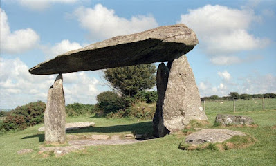
This evening I watched a documentary presented by Alice Roberts. I don’t think I have watched a programme presented by Dr Roberts that hasn’t been interesting, and this one was no different, except that the most interesting thing wasn’t strictly the topic. The documentary was about the bluestones of stonehenge, but it strayed ever so slightly to Pentre Ifan in Wales were I was introduced to Dolmens. These are Neolithic structures, which predate Stonehenge. There are lots of them around the world and some are thought to be around 7,000 years old. The Dolmen at Pentre Ifan is a spectacular example, whose massive capstone appears to float above the tips of three standing stones. I expect that’s why I noticed it and why Alice Roberts chose that example.


Archaeologists believe that Dolmens were ancestral tombs, because scattered human remains are often found between the standing stones. Some also believe that they were originally buried beneath a mound of earth or smaller stones.

Interesting as these conjectures are I can’t get past the graceful form of the structure. I suspect that archaeologists, for the most part, take for granted that the monument stands, while going to great lengths to try and understand how it got there and how it was built. I think I understand why this is, but there is a certain irony that for such an old object so much more effort is expended on the temporal than the permanent [1].

To me the fact that Pentre Ifan is standing at all is more interesting and is the subject of this post. Maybe on another occasion I’ll fall in to line with everyone else and have a go at speculating how such structures are built, but not today.

I should of course pause to note that I have never seen a Dolmen in person, nor do I really know anything about them, other than tonight’s brief introduction. I am keen to remedy that and will aim to visit some examples when the covid-19 lock-down has ended, however that isn’t going to stop me from donning my engineering hat and doing some speculation of my own. I shall be doing so based on a few images I have pulled off the internet; what could possibly go wrong?

I am going to start with the assumption that the stones are igneous rocks, because they have that appearance and because there are outcrops in the the relevant part of Wales. This ought to make the rock relatively strong; though like any rock it will be brittle and weak in tension.

There is evidence of horizontal fractures in the capping stone and equivalent vertical features in the standing stones. Structurally this is not a terribly efficient arrangement. A stronger arrangement would be to align planes of weakness in the standing stones horizontally so that they are squashed together. For the capping stone it would have been better to align them vertically so as to avoid separation due to shear flow generated by bending forces.

I suspect that this was not done, because creating the great slabs of stone required cleaving them from the parent rock by exploiting the noted weaknesses. Without them stone-age workmen would have had difficulty creating such slabs with primitive tools.

The next thing I notice is that the capping stone appears to be fatter at one end than the other and that the soffit appears to have been cleaved as it progresses towards the thin end. I suspect that it was not originally so.

The fat end is supported by two standing stones, while the thin end is carried by one. In the short axis the fat end of the capping stone can bridge laterally between two close supports. It can possibly do this in direct shear and without inducing bending.

Conversely, in the longitudinal direction the capping stone must span almost 5 meters between the single and double support. This almost certainly results in it experiencing bending. As has been seen in prior posts bending causes the top surface of a beam to experience compression and the soffit to experience tension. 

In order for this to happen a beam will also experience a laminar shear flow in the horizontal direction. This can be understood by imagining a beam divided into horizontal slices. For tension to be experienced on the soffit while compression is experienced on top it is necessary for the imaginary slices to slip past each other.

The consequence of these actions appears to be evident in the structure. Since stone does not deal well with tension it is inevitable that small cracks must have developed in the soffit. There would also have been lateral movement along the rock’s natural horizontal weaknesses. It is conceivable that together these effects led to the soffit spalling, however it is more likely that they were abetted by other effects too.


Rainwater will have soaked through the top surface of the slab and migrated under gravity to the soffit. While moisture would evaporate quickly from the top the soffit would remain in the shade helping to keep the stone damp and wet. Persistent dampness will have weakened the rock structure and freeze thaw action would have exploited the many small cracks and natural weaknesses. Eventually the fractured rock would spall until it arrived at a horizontal plane of weakness whereupon the process would start again.

Perhaps another aggravating factor would be expansion and contraction due to the cycle of heating and cooling. Since only the top surface is exposed to the sun there is likely to be a thermal gradient in the capping stone as it warms. During the day the top of the stone would expand relative to the soffit and thereby start to close some of the soffit cracks. Conversely, during the night it would start to contract and thereby re-open the soffit cracks. Thus, by repetition the soffit would slowly be fatigued and further cracks induced.

When considering thermal effects it is worth noting that having only three small points of contact between the capping and standing stones is probably beneficial, because the soffit is free to articulate. More severe cracking would be much more likely if the top surface were free to expand and contract while the soffit was held in place by more restrictive contact. 

It would therefore seem that there is a good explanation as to why the capping stone is fatter at one end than the other, and all else being equal, by what mechanism it will eventually fail.


The standing stones appear to carry the capping stone effortlessly. The fact that they do so with such small points of contact would suggest the compressive strength of the stone must be relatively high. That said, it is assumed that the contact surfaces could not have been prepared to a modern standard and therefore the distribution of load will not be entirely even. This will have allowed load concentrations to be formed which may over time pry and fracture the rock locally.

This is important because compression in the standing stones will cause lateral bursting forces to develop due to passion’s ratio [this is another concept we have seen before]. Within the body of the stone compressive stress is generally low and therefore the bursting forces have little effect, however where load is concentrated stresses are higher. If such stresses coincide with a vertical plane of weakness it could encourage the bursting forces to form a split in the rock. As with the capping stones this could be exacerbated, either by moisture penetration, or by bending induced by one side of the rock being warmed faster than the other. There does seem to be some evidence of such processes at work on the surface of the standing stones.

Another facet of the pictured Dolmen is how it maintains lateral stability. It is self evident that there is no rotational resistance at the junctions between the capping stone and its supports, therefore we must conclude that the standing stones must cantilever from ground level. Since the capping stone bears heavily upon them there will be sufficient friction generated to share lateral load between the standing stones according to their stiffness.

Lateral loads would come from the wind and to a lesser extent thermal effects. There also appears to be a slight incline to the capping stone, which would imply there is a resultant lateral load, due to the stone’s self-weight, to be resisted.

Something else that is structurally relevant, though I am unsure whether it was intended, is the orientation of the standing stones. The two stones at one end are orientated perpendicular to the single stone at the other. Strength being proportional to the cube of depth this arrangement presents the full depth of at least one stone in each orthogonal direction, thus maximising cantilever action in both.

It is also interesting that the end supported by two stones is aligned with the noted incline to the caping stone, thus maximising resistance to the permanent lateral load. The possibility that this was intended is intriguing.

A different explanation would be that since one end of the structure has two supports, and the other just one, there could have been differential settlement. Assuming this were the case the narrow supports would again have been beneficial, because they would have allowed the capping stone to rotate and find a new point of equilibrium. Alternatively, more substantial supports would have likely led to fracture. I have no idea what the bearing strata beneath the standing stones is like, but in the absence of further evidence the mechanism for differential settlement seems plausible.

Of course it is also possible that the fractured soffit could have contributed to creating the observed incline too.

While the depth of embedment of the standing stones is not clear from viewing the surface it seems reasonable to assume that it must be substantial to ensure there is sufficient passive resistance to prevent overturning or sliding of the stones. In a uniform soil it would also be reasonable to assume that bearing pressure would increase with depth.

On paper it is perhaps possible that the stones could be mounted near the ground surface with stability being maintained by their shear size and mass. In the real world this does not seem plausible as the surface of the ground is prone to become waterlogged, there is also the possibility of frost action. Either of these effects could be sufficient to topple the stones.

Two further practical matters exist. Firstly, a shallow footing would be vulnerable to digging near the base when bones were to be buried. 

Secondly, and perhaps more importantly, the processes of standing large stones on end without a crane, or other modern equipment, would seem to make it necessary to tip them into a hole. If said hole were then packed tight with backfill it would lock the stones in place allowing them to behave as cantilevers.

Here I run the risk of getting into the question of how the stones were erected and I said I wasn’t going to do that. I best stop here.


[1] I base this thought on working with a few archaeologists and the number of documentaries there are about erecting Stonehenge, rather than any proper search of the archaeological literature.


Sunday, February 14, 2021

On Accidental Bridges

The robustness of brick walls


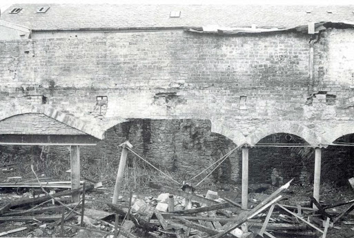
I came across this rather interesting photo, which shows the remains of a partially demolished nineteenth century mill. 


The picture is dominated by a large brick wall, which is suspended above ground level. The original load-path for its support appears to have been an arcade consisting of cast iron columns carried on masonry arches. 

To the left of the image one of the arches has been altered. The profile of its voussoirs has been straightened on one side and the arch infilled with modern brickwork. The infill brickwork is in turn supported on a modern beam and post structure, which is likely formed of hot rolled steelwork.

Below the centre of the wall two of the cast iron columns have been pushed over. The one on the left is clearly visible, while the one on the right is a little harder to pick out. Its head can be detected, because it is still connected to the wrought iron rods that would have been used to resist thrusts at its abutments. To the right of the photo the rods can still be seen linking the remaining iron columns.

It is also evident that the masonry arches which would have been carried by the missing columns have collapsed. It is assumed that rubble, which can be seen at the base of the picture, is what remains of them.

What is of course remarkable is that the brick wall continues to stand. It has found a way of bridging between the steel column on the left and the cast iron column on the right. This is interesting for several reasons.

Since the span is roughly equal to the height of the wall it is reasonable to assume that it has achieved this feat by acting as a deep beam. Were the deep beam made of concrete it would be normal to assess it using a ‘strut and tie’ model. This means imagining a triangular load path in the wall. The two vertices of the triangle form compressive struts, which are sat over the supporting columns, while reinforcement in the base of the wall would complete the triangle by resisting lateral thrusts from the inclined struts. An alternative way of considering this model would be to think of it as a tied arch, as the principle would be similar. Indeed, post failure the residual brickwork appears to have formed a crude arch between the column supports.

In this case there is no concrete and no reinforcement, because the wall is made of brick. Brick is good in compression, which would seem to make either an arch, or compressive struts, a viable load path, however there is no equivalent for the reinforcement, which is required to complete the triangle. 

Brickwork is poor in tension and therefore the base of the wall ought to have failed, however there seems little evidence of distress other than the smaller arches giving way to form a larger, if somewhat makeshift arch.

This means the deep beam must, on this occasion, have a different mechanism for resisting lateral thrust. Two options seem plausible, though one seems more likely than the other. 

It is possible that there are rigid load-resisting structures located just out of picture on either side of the image, however if this were the case then there would be no need for the wrought iron ties, which originally held the column heads together.

It seems more likely that the weight of the brick located above the arch supports is sufficient to divert the arch thrusts back to the vertical i.e. it behaves like heavy bridge abutments. Both headers and stretchers can be seen in the brickwork suggesting that the wall is at least a full brick thick and would therefore be relatively heavy.

Looking carefully at the image there is also evidence of pockets in the brickwork, which would have seated beams in the wall. In fact the remains of an I-shaped steel beam can still be seen embedded on the left hand side. It was presumably easier to cut the beam off at the support than to completely remove it during prior alteration works. This may be relevant because the load carried by the wall must have been reduced. This in turn means the thrust is less.

Since two columns are missing we would ordinarily expect those which remain to take 100% more load. For this reason a reduction in load carried by the wall is of significant benefit to the columns too.

So it would seem that a structure whose intended load-path has been compromised has managed to find an alternative load-path demonstrating rather well that structures will exhaust all possible ways of standing before they collapses.

This does not mean that we would necessarily wish to rely on this load path in the long-term, but nevertheless it is a reminder for engineers that there is more than one way of looking at a problem….in this case an accidental bridge.


Sunday, December 20, 2020

On Breaking Trains

Or why systems need to be robust


On 22 October 1895 a steam locomotive approached its Paris terminus slightly faster than normal hoping to make up lost time. Except that rather than stopping at Gare Montparnasse, as planned, it crashed through the end of the platform, over the concourse, through the station facade and down onto Place de Renne a full storey below. Apparently, the only casualty was a woman who had the misfortune to be standing in the street and was struck by falling masonry.


The question arises, why did the train fail to stop? 

Following the subsequent accident inquiry the hapless locomotive driver is reported to have been fined 50 francs and sentenced to two months in gaol, because he approached the station too fast. One of the guards was fined 25 francs, because he was apparently too pre-occupied with paperwork to apply the hand brake.

One might assume that this was all there was to it, however as it turns out the driver and the guard were not solely responsible. 

It is also believed that the train’s Westinghouse air brakes had rather tragically failed, which seems to me a rather more significant event, but not for the reason that you might think.

Trains were of course a wonderful invention, which had transformed the world by making mass transit possible over long distances. The trouble with steam locomotives, at least in their infancy, was that nobody was quite sure how to stop them.

They travelled faster than anyone had travelled before, but were also big and heavy. The locomotive had a hard enough time stopping itself let alone the passenger cars and goods wagons that followed behind. It was not unusual for the following carriages to catch up with the locomotive when the brakes were applied causing them to collide, first with each other, and then with the back of the locomotive.

In order to make the train stop within a reasonable distance it was realised that brakes had to be added to the carriages too. The obvious difficulty was how to apply the brakes on the locomotive, and all the carriages, at the same time.

Initial solutions were somewhat rudimentary. In the United States a brake man sat on top of the first carriage. When the driver blew the train’s whistle he was responsible for applying the brake on the first carriage. He was then required to run down the roof before leaping onto the next carriage whereupon he applied its brake. This process was repeated until he reached the back of the train. This was, as one could imagine, a rather precarious job and not surprisingly there were many casualties.

The American entrepreneur and engineer George Westinghouse, like everyone else, saw the problem. Unlike everyone else, Westinghouse came up with a solution. He joined the carriages together with airtight hoses and used compressed air to apply the carriage brakes almost simultaneously. The system worked brilliantly, bringing trains to a halt with great effect. For many people the idea of stopping a large heavy object travelling at high speed with nothing more than air had initially seemed a little crazy. When it worked Westinghouse was rightly seen as a genius.

Except that there was a problem that no one at the time had foreseen. If there was a loss of air pressure, due to leak in the system, the breaks wouldn’t work. It is believed that this is exactly what happened at Gare Montparnasse. Understandably, fail safe systems where added to subsequent designs.

Knowing this story I was rather intrigued by the heritage steam train that I happened across while on a recent camping trip in Cumbria. In the images below you can see a red  pipe on the back of the locomotive, which passes between all the carriages and can also be seen at the tail of the last carriage. There is also a small pressure vessel beneath one of the seats in each carriage, but you can’t see that in these pictures.


In case you haven’t guessed I rather suspect that what we have here is a rather old fashioned air-break system not unlike those used on early locomotives. I didn’t get chance to investigate further, but I am going to assume its the mark two version.

The next question is what this has to do with a structural engineering blog? The reason I decided to write, other than the fact that I found it interesting, is the principle of robustness. An otherwise brilliant idea, which made a big difference to the safety of trains, was, in its earliest conception, flawed. It wasn’t flawed because it didn’t work. It was flawed because it was vulnerable to miss-use or accidental damage. In short it was not a robust system.

This ought to be a concept familiar to all structural engineers. The archetypal accident, at least in the UK, was the partial collapse of a 22 storey tower block in 1968. The tower stood quite happily until a gas explosion blew out one of its walls, causing the walls and floors above to collapse like a pack of cards. Unfortunately the component parts were not adequately tied together and were therefore unable to bridge over the damaged section of the structure. Four people died and 17 were injured.

The concept of robustness is not necessarily aimed at particular events or circumstances, rather it is intended to provide a degree of resilience against the unforeseen and the unknown. It now seems obvious that structures should not fail the moment the design load case has been exceeded, but it was not always so. 

Of course a supplementary question one might ask is how robust does a structure need to be? How robust is enough? That’s a difficult question to answer, but an ingenuous formulation has been devised, which has come to be known as the principal of ‘disproportionate collapse’. Put simply this means that any damage suffered by a building should not be disproportionate to the event that caused it.

So what is considered proportionate? That’s a rather big question, which perhaps needs its own post at some future point. 


Sunday, September 20, 2020

On Bell Towers & Skipping Ropes

For many years there has been considerable academic interest in the structural behaviour of masonry bell towers during earthquakes and whether their bells help or hinder performance. The observed level of interest is for the most part driven by the fact that masonry belfries are often amongst the structures most severely damaged when an earthquake strikes.

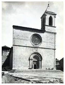
One such structure is the belfry at San Silvestro in L’Aquila Italy, which is pictured below as it was in 1906. It was damaged by an earthquake in 2009, however repair works continued until 2019. One of the difficulties of designing such repairs, or indeed pre-emptive strengthening, is the inherent difficulty of predicting how the structure will respond to the dynamic forces that seismic events generate. No two structures behave in the same way and therefore each one presents a fresh puzzle. 


When a friend, and director of an MSc course in building conservation, recently passed me an academic paper with the somewhat catchy title ‘Identification and Model Update of the Dynamic Properties of the San Silvestro Belfry in L’Aquila and Estimation of Bell’s Dynamic Actions’, I read it with interest.

I confess that the mathematics contained in the paper are likely now beyond me. I am too far removed from doing analytical work in that depth.

That said, this is not always a bad thing as distance can sometimes bring perspective. In my view the most important diagnostic information in the paper is contained in figures 7a and 7b, because we can postulate from the depicted crack patterns what the complex mathematics mean.

That said everything that follows is complete speculation on my part. I have never visited the church, though I would like to, and I have no intimate knowledge of the way in which it was built. My entire speculation is based upon the reported pattern of cracking and some experience of designing buildings to resist earthquakes. 

The base of the tower is locked to the ground and therefore travels back and forth at the same rate as the quake shakes the ground. Since the tower is not infinitely stiff it begins to flex when the ground and tower base start to move. The time taken to flex means that the lateral movement at the top of the tower lags behind the base of the tower. At some point the base of the tower, which was moving left starts to move right, but due to the effect of lag the top of the tower is still moving left. The top and bottom of the tower are now out of sync. 

Thus, a snaking motion is set up in the tower, resulting in the crack pattern shown. It’s a bit like the wave you can generate in a skipping rope when you move the end up and down rapidly.  

In mathematical terms we might say the period of the tower is greater than the period of the earthquake. 

The maths in the paper essentially goes on to explain that the bell in the tower has no material effect on the period of the tower. This is because the bell’s mass, and hence momentum, is insufficient to overcome the stiffness and mass of the tower, even although the tower has flexed and cracked and movement at the top has lagged the base. 

Unfortunately structures like this are not at all like modern ones in the sense that they don’t have clearly discernible load paths and consistent properties. It follows that academics will always find it difficult to determine the stiffness, and hence period, of a given tower with accuracy i.e. the analytical answer can only be as accurate as the estimation of stiffness. All the maths in the world doesn’t overcome that problem. It’s painstaking detective work that is required. In fairness I think the authors of the catchily titled paper acknowledge this difficulty. 

I may well have over simplified the problem. For example, I haven’t mentioned the effect the rest of the church has, or what effect the windows in the bell tower have, or whether the tower’s stiffness changes over its height. In fact there are lots of things I haven’t mentioned. I am simply making an observation that the reported pattern of cracking is consistent with the explanation I have set out…… at least that's what I think. Feel free to differ.

Sunday, September 13, 2020

On Garden Fences

The photograph below is a picture of a garden fence at my parents home. It divides a portion of their garden from their neighbours’. The fence is supported from a series of four square timber posts embedded in the ground. Horizontal timber battens are fixed to the timber posts both at the head and base of each post. Timber boarding is then fixed alternately either side of the battens. 


In one sense the fence looks unremarkable, but looks can be deceiving. On closer inspection it is evident that something is wrong. A vertical split has begun to appear at the head of the two middle posts. For the curious mind the question arises as to why this has happened and why only to the middle posts?

For those who have read my prior post titled ‘On Cladding Garden Sheds’ you may have an idea what the cause may be. For those who haven’t its worth re-capping. That said, while part of the mechanism is similar, ultimately the load-path is actually different.

When a tree is felled its moisture content could well be 100%. As it starts to dry out free water will evaporate from its cells until it reaches somewhere between 25 and 35%. Beyond this point water is lost from the cell walls of the timber fibres themselves. This causes the timber to shrink’.

It seems self evident that on warm days the timbers forming the fence begin to dry out causing all of the timbers to shrink. The battens are fixed rigidly to the posts supporting the fence; in the case  of the two middle post there is one either side. If both of the battens shrink at the same rate then they will pull on the middle posts in equal, but opposite directions causing a split to form in each.

Conversely the two outside posts have a timber batten fixed to one side only. They are therefore pulled from one side only. Since there is no counter pull these posts are free to flex. It follows that there are no splits in the two outside posts.

If the mechanism described above is correct the next obvious question is; why there is much less evidence of splits at the base of the fence; there are perhaps hairline splits at most? If all the battens are fixed in the same way why does the base not match the head of the fence?

There are several possible answers to this question. The true answer may be a combination of each. 

Firstly, the base of the fence is closer to the ground and therefore when it rains timbers in this location will receive splash back. Secondly, when it rains water will tend to run down the fence under gravity and will collect near the base of the fence. These factors would make the timber at the bottom likely to be more wet than those at the top.

A third factor would be that sunlight would reach the top of the fence for a longer period of the day and the base would tend to be in shadow for longer. Fourthly, there is dwarf wall built on the neighbours side of the fence located close to the base of the fence. This side of the fence would definitely be in shade for longer. When the sun shines from the neighbours side of the fence this effect would be exaggerated. Together these two effects mean that timber at the base of the fence would dry out more slowly.

Taken together it is self-evident that the timbers at the base of the fence are on average wetter than those at the top thus providing less potential for shrinkage. It follows that the forces experienced by the timber posts are less at the base.

It is also possible that since the bottom of the fence is close to the point at which the posts are embedded in the ground, the posts are harder to split due to their confinement by the ground.

The question now arises how could the fence builder have prevented the posts from splitting. The obvious answer would have been to double up the internal fence posts to create a movement joint, but of course that would cost more money. The moral of the story is that being cheaper carries its own price.


Postscript

For the most observant it is also interesting to note that the nails fixing the battens are corroded and stains are starting to appear in the timber. Conversely the nails connecting the timber boarding to the battens are not corroding.

One can see that the nail heads vary in size suggesting that they are of a different type. It would appear that the smaller nails used to connect the vertical boards are of the stainless steel variety while those connecting the battens to the posts are not. 


Sunday, August 23, 2020

On Cladding Garden Sheds

Sometimes interesting structural load paths present themselves in unexpected places. The photograph below is such an example. It shows a cross section of timber cladding boards at the door threshold on my parent’s shed, which is located at the bottom of their garden behind the garage. You can see the end of the garage through the glass panels in the door. 


What is interesting is trying to understand why the timber cladding board in the centre of the picture has started to cup, which has in turn caused the tongue and groove’s cut into the board’s long edges to begin separating from adjacent boards

This requires us to know something about how trees are converted into boards and why this affects the way that they move and warp. It also requires us to understand how this affects the way cladding boards should be detailed.

There are three methods of converting a log into boards. The most common is known as plain / flat-sawn, which essentially involves slicing the log into vertical strips. It is the most common choice because it minimises the amount of timber wastage and maximises the number of boards. It is therefore cheap.

The second most common method is known as quarter-sawn. As the name suggests this involves cutting the log into quarters and then flat-sawing each quarter. This produces a little more waste than conventional, flat-sawn timber and is therefore more expensive.

Rift-sawn boards are reasonably uncommon, because there is high waste and therefore they are expensive. In this case the boards are sawn in a radial pattern.

The reason that various methods of forming boards exist is because they each intersect a tree’s growth rings in different way. Flat-sawn boards are cut tangential to the growth rings; rift-sawn boards are cut radially and quarter-sawn somewhere in between. The benefit this brings will shortly become clear. 


When a tree is felled its moisture content could well be 100%. As it starts to dry out free water will evaporate from its cells until it reaches somewhere between 25 and 35%. Beyond this point water is lost from the cell walls of the timber fibres themselves. This causes the timber to shrink. Since shrinkage tangential to the growth rings is roughly twice that in the radial direction the method used to form the boards becomes really important.

Flat-sawn boards will distort out of plane causing the middle of the boards to move towards what would have been the heart of the tree. Quarter-sawn boards will tend to warp in plane. In contrast to both other forms of cut rift-sawn boards tend to be dimensional stable.

Knowing what we now do we can return to the garden shed cladding. 

If we look closely at the board edges we can detect from the pattern of growth rings that the boards were flat-sawn. They were always going to vulnerable to distortion. If we look even more carefully we can also see that the growth rings in the middle board are orientated in the opposite direction to the boards either side. This has had the effect of causing the middle board to pull the edges of the two adjacent boards outwards.

This has of course been exacerbated, because the builder did not understand how to fix the boards so as to minimise the effect of shrinkage. The photo above shows that the boards have tongue and groove edges that are meant to interlock while being allowed to slip past each other. 

To minimise the effect of shrinkage this arrangement is supposed to be nailed through the upper shoulder of each board with the lower edge being free to move while being restrained by the tongue and groove joint at the bottom of the board.

Of course you can see in the photo below that the clown that built this structure has double nailed the centre portion of each board forcing the shrinkage movements to the outer edges. 


That clown was of course a teenager who later became an engineer and decided to write an engineering blog.

On Ice Shelf Cracking

Tension Cracks in the Brunt Ice Shelf Yesterday the BBC news website published images showing a large section of the Brunt ice shelf in Ant...