Showing posts with label foundations. Show all posts

Sunday, January 3, 2021

On Negative Skin Friction

An unusual case of piling


Many years ago I designed a building in central London, which was later occupied by a well known tech giant. There were many interesting features to the building, however perhaps the most interesting is concealed from view below ground level.

Like many large buildings in London its weight is too heavy to be borne on shallow foundations therefore concrete piles embedded deep into the soft London clay were required.

The structure was to be built on the site of a prior building which had also been piled. We soon discovered that is was going to prove difficult to match new pile positions with proposed column positions, because the existing ones were always in the way, though never quite in the right place we needed them. Grubbing out the existing piles was very expensive and would have loosened the soils somewhat. We decided to build a deep raft on top of the existing piles that would allow us to transfer new load into them from our planned column positions. Justification of the the existing pile’s load capacity was rather interesting, but that is not the topic on this occasion.

The footprint of the new building was required to extend beyond that of its predecessor and therefore a line of new piles was required in front of the existing ones. This was to prove an opportunity to use some creativity, because we knew that this part of the site fell within the influence zone of the planned Cross Rail underground tunnels. The route of the tunnels had been secured with legislation for many years.

To understand the influence this would have it is first beneficial to understand how friction piles work and what the effect of future tunnelling would be.

Friction piles, as the name would suggest, resist load by generating friction between the surface of the pile and the surrounding ground. The larger the circumference of the pile and the longer the pile is the more friction will be generated. Consider trying to push a tent peg into the ground or hammering in a fence post. It becomes progressively harder the deeper they penetrate into the ground; this is friction in action. It is a powerful force.

Tunnelling is a complex operation, but in principle it involved pushing a circular shield into the ground and digging the ground out within the safety shield, which prevents the ceiling from collapsing. A structural ring is then constructed inside the shield before it is advanced to the next section of the tunnel. When the shield moves on the ground fills the gap that is left behind by settling on to the newly constructed structural ring. As the tunnel progresses a wave of settlement follows the head of the tunnel.

An interesting thing happens when concrete piles fall within the zone of settlement. As the ground settles and drops it tugs down on the embedded piles. This action pulls the piles downwards due to friction between the ground and the pile shaft. In other words the tunnelling has caused friction to work in reverse. Instead of friction pushing against the weight of the structure it is now acting in concert with the weight of the building ‘sucking’ it into the ground. This is known as ‘negative skin friction’ and it would be bad for the building, particularly of the rest of the building, which is out with the tunnelling zone, stays where it is and does not settle.


The conventional way to overcome this problem is to sleeve the piles in steel tubes over the full length of the tunnel’s zone of influence. To ensure the piles still have capacity to resist the building’s weight they extend beyond the sleeves and are embedded below the depth of the tunnel. This means that when friction reverses the steel sleeve is tugged downwards, but the pile remains static inside the sleeve while load resistance continues to be provided by friction generated below the tunnel.

This is a rather expensive option, because each pile needs a long steel sleeve. We therefore decided to think about whether we could design the foundations without sleeves. If we could it would save both time and money for the client.

We ‘war gamed’ many scenarios, but eventually reasoned that, providing the piles extended below the depth of the planned tunnels, the most likely scenario was that the expected negative skin friction would cause an ‘apparent’ increase in the weight of the building. We were confident that we could design the piles to deal with that ‘apparent’ increase and so that’s what we did. It took a while to design, and being an unconventional approach, it also took a while to obtain formal approval.

It all seemed very theoretical at the time. Cross Rail had been spoken of for years, but had never been realised. Many thought it would never happen. Of course that view has since changed. Cross Rail is due to become operational in 2022. So far the building is still standing quite happily; our hard work appears to have paid off.

Something also worth mentioning; the route of the tunnels originally passed beneath the existing piles too, which would not have done them any good at all. Within the approval process for our new design we therefore proposed that they be altered to avoid damaging the existing foundations. Our proposal was eventually accepted and the layout of the tunnels was changed. In this location they run on top of each other instead of side by side.


Sunday, December 6, 2020

On Pile Caps [again]

The single pile cap


At the conclusion of my prior post ‘On Pile Caps’ I posed the question; would a single column supported by a single pile result in a straightforward pile cap design? It has to, right? The load-path is so obviously simple. Load passes from the column directly into the cap and from there directly into the pile. It’s surely a clear example of load transfer by direct bearing? There isn’t any bridging to be done.

We are only one paragraph into this post so patently there’s something else going on. The question is what? To answer that question we need to take a step back and start thinking about the mechanics of materials in a more nuanced way.

We are going to do this by putting concrete aside for moment and considering some other materials that make it easier to visualise what might be going on.

When a bar or rod is loaded in tension it will start to stretch in the direction of the load. The amount it stretches is proportional to the material’s stiffness. What is perhaps less obvious is that while the rod stretches it is also experiencing a lateral contraction perpendicular to the action of the load.

You can actually see this happen if you stretch an elastic band, however in stiffer materials the phenomenon is harder to detect without instrumentation.

We can also reverse this process. If we take a short rod [to ensure it does not buckle] and apply a compressive load it will start to squash in the direction of the load. As before the amount it squashes is proportional to the materials stiffness. Since we are reversing the load’s direction we can reasonably expect the rod to experience a lateral expansion perpendicular to the direction of the applied load.

This phenomenon can also be seen visually if, for example, you were to squash a bathroom sponge.

In engineering terminology the amount a material shortens or lengthens is known as strain. The ratio of lateral strain to axial strain is known as Poisson’s ratio after the French Mathematician and Physicist Simeon Poisson.

Now, since lateral strain results from the application of a vertical strain [tensile or compressive] we can logically deduce that there must also be a lateral force, which is proportional to the applied vertical load. The relationship between vertical and lateral load is of course Poisson’s ratio. Posssion’s ratio for concrete is approximately 0.2, which means that the magnitude of lateral load is roughly 20% of the vertical load.

If we now return to our pile cap we can deduce that there is in fact a limit to the bearing pressure that may be applied to the pile cap by the column. As the applied vertical load increases the lateral load will also increase causing the sides of the cap to push apart. This is of course a tensile action, which we know concrete does not like. It follows that the point is quickly reached where the sides of the pile cap will literally burst apart. To prevent this from happening containment reinforcement is required to resist the tensile forces.

Having established the effect of Poisson’s ratio we are still not quite done.

One of the practicalities of pile design, particularly friction piles, [see prior post] is that their circumference has to be large or there will be insufficient friction to prevent it from sinking into the ground. This means that the pile diameter is likely to be much bigger than the column diameter. 

The implication is that load must spread from beneath the column into the pile. If the difference in diameter is sufficiently large then a ‘strut and tie’ arrangement is set up in the pile cap, which is akin to that described in my prior post about two-pile caps.


It turns out that passing load through a single pile cap has a more complicated load-path than you might think, because the effect of Posison’s ratio and load spreading must both considered.


Sunday, November 29, 2020

On Pile Caps

Different ways of tackling the same problem


The soil beneath some buildings is of insufficient stiffness to support the weight of heavy buildings. The solution is to carry their weight on piles, which extend deep underground. In some cases the piles are embedded in rock and are known as end bearing. In other cases rock is located far below the ground surface and therefore piles rely on generating friction with the ground. 

When more than one pile is require to carry a column’s load it is necessary to construct a bridge between them on which the column may sit. This concrete bridge is known as a pile cap. Pile caps are therefore important structures that lie unseen and unnoticed below ground level.

Since they are unseen pile caps are simple functional structures without a care for visual taste or aesthetic consideration. They are amongst the simplest structures an engineer can design.....or so you might think.

The real world turns out to be more complicated than that, because nobody is entirely sure how pile caps work. This is a surprising fact, even for some engineers, who assume their well worn methods of design represent absolute truth.

This should not be a surprise, because most will know that there are two standard methods of design; the so-called ‘strut and tie method’ and the ‘beam theory method’. It is curious that some see no significance in the fact that two methods exist. Fewer still seem to realise that we are not limited to two; there are in fact many more ways of considering the problem. 

When you appreciate this you can see different ways of analysing all sorts of problems. It liberates your mind from the sort of engineering that cannot see past the prescriptive methods set down in text books and codes of practise. It gives the engineer licence to explore other load-paths and freedom to innovate. That said, let’s not get ahead of ourselves.

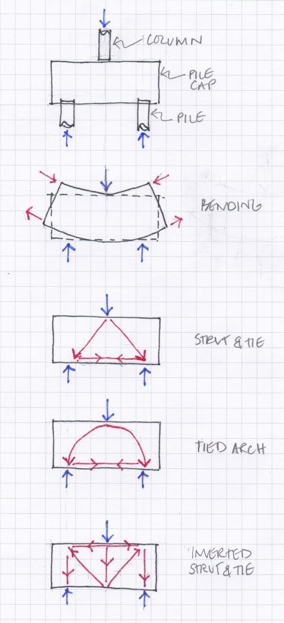
Perhaps one of the simplest structures conceivable is a column supported on two piles with a two-pile cap distributing the load evenly. We know the cap distributes the load; the question is how?

Let’s look at ‘beam theory’ first. Using this approach we assume the cap is a large beam made of reinforced concrete, which behaves much like the joists in a house. As the beam is loaded it begins to bend i.e. it takes up the form of a curve. When it does so the top surface necessarily becomes shorter and the bottom surface becomes longer. Self-evidently the surface that is becoming shorter is being squashed and is therefore in compression and the surface that is being stretched must therefore be in tension.

Every engineer knows that concrete is strong in compression, but weak in tension. In fact concrete will begin to crack when the tensile forces are still quite small. For this reason concrete is reinforced with steel bars, which are strong and resilient in tension. Bars are placed into the zones where tension exists. In this case at the bottom of the pile cap.

Now let’s look at the alternative ‘strut and tie’ model. Using this approach the engineer assumes the existence of an imaginary triangle with it peak touching the top surface of the cap, just below the column, and its base stretched over the piles below.

It is not difficult to imagine fifty percent of the  column’s load traveling down each leg of the triangle by means of compression. These are the eponymous struts. One might be tempted to assume that since the load travels by compression there is no need of reinforcement, however we must pay close attention to the angle between the two struts. Since they are not vertically aligned our imaginary triangle struts must have a horizontal component to the force which they carry. This horizontal force wishes to push the two legs apart, much like the force that causes a house of cards to spread and fall.

To prevent our imaginary triangle from spreading there must be a tie, which is conveniently provided by the bottom chord of the triangle. Again, since concrete cannot resist tension, steel reinforcing bars are inserted into the bottom of the concrete. Curiously, the quantity of steel that this approach requires is different to that derived by beam theory.

Now that we have examined the two ‘normal methods’ we can of course try some other methods. Instead of an imaginary triangle, why not assume an imaginary arch with a reinforced tie at the base?

Another approach would be to turn the ‘strut and tie’ model upside down and assume an inverted triangle. This is an interesting, if slightly convoluted, concept, which would be tricky to build, but is perfectly tenable. In this example tension bars would extend from the top corners of the pile cap down to the middle of the bottom surface. The legs of the triangle would be loaded in tension and would therefor pull the top surface together forcing it into compression.

The reason this approach is more convoluted is because the peak of the imaginary triangle does not sit directly below the column and its base does not sit directly above the piles. To complete the load-path it is therefore necessary to imagine a strut in the middle of the triangle that transfers load from the column down to the peak of the triangle. Two more struts are requires, one at either side of the base to transfer load into the piles.

Of course, if we can invert the ‘strut and tie’ we can also invert the ‘arch model’. For similar reasons this is also a tricky arrangement to build, but perfectly viable.

We now have four methods by which we could potentially transfer load from a single column into two piles. There are many more. For example, instead of a ‘strut and tie’ we could consider an imaginary truss. When we do so it is not difficult to imagine the many and varied ways in which the internal chords of the truss might be arranged.


So which method is the ‘real’ load path by which the pile cap actually transfers load. The truth is it doesn’t actually matter. So long as the engineer has designed at least one way in which it could work the structure will stand. The contractor who has to build it may not see it that way, but for the purposes of this exercise that does not matter. The point is that for even the simplest of structures many possible load-paths exist and that is an interesting conclusion.

Perhaps more interesting still is what happens when we consider a single column and a single pile. Surely that has to be straightforward, right? I’ll answer that question next time.

On Ice Shelf Cracking

Tension Cracks in the Brunt Ice Shelf Yesterday the BBC news website published images showing a large section of the Brunt ice shelf in Ant...