Showing posts with label bridges. Show all posts

Sunday, July 4, 2021

On Britannia Bridge

An empirical masterpiece


When I studied engineering at university one of the structures that was frequently put forward by Professors, as an excellent example of structural design was Britannia Bridge. Throughout my time at university and probably for a time afterwards I didn’t really understand why. It didn’t seem a particularly great design to me. I don’t suppose for one moment that was my Professors’ fault; I had good teachers. I suspect it was more likely that I wasn’t paying sufficient attention.


Though I was unquestionably wrong, if I give my younger self the benefit of the doubt, my view was not entirely without merit. Firstly, I had not seen lots of other bridges old or modern that resembled Britannia; suggesting that despite its supposed brilliance few saw fit to copy it
[1]. Secondly, passing steam trains through a tubular structure, as Britannia did, didn’t seem like a good idea to me. The smoke and soot must have been pretty unbearable. Furthermore, the integrity of the bridge was compromised by fire in 1970, which brought about its eventual demise. It therefore failed in its primary purpose of carrying trains from Wales to Anglesey. 170 years of service is by most accounts rather good, but I reasoned this was luck. What would have happened had the fire occurred earlier in its life? 

Notwithstanding all of this, Britannia Bridge was, in my humble opinion, ugly. My architect friends might well quip that this is exactly what to expect from a bridge designed by an engineer. I beg to differ, but that debate is for another day.

Having got that historical baggage off my chest I am now, as you might have guessed, wholly convinced of Britannia’s brilliance and it’s aesthetic has sort of grown on me. I’m not saying it has become easy on the eye; rather an appreciation of how it works and how it came to be has resulted in a greater appreciation of its aesthetic.

So why did I change my view of Britannia’s structural design and what was it that persuaded me? Much like students today, my younger self lacked an appreciation of context and when judging the achievements of the past context is everything.

Thomas Telford, the first president of the Institution of Civil Engineers, completed the Menai Strait suspension bridge in 1826. At that time it held the record for the longest suspended span in the world and it is an elegant and beautiful bridge. That said Telford’s masterpiece [perhaps the subject of a future post] was not without problems. It suffered aerodynamically and was damaged on several occasions before being stiffened. 

When Robert Stephenson was faced with the problem of bridging the Menai Strait for the Chester & Holyhead railway a suspension bridge, like Telford’s, was not considered stiff enough to carry the weight of steam locomotives [the suspension form was still in its infancy].

The obvious answer would have been to construct intermediate piers from which arch centerings could be erected, however the currents in the strait were considered to be treacherous and therefore the Admiralty insisted that there be no obstructions placed in the channel, which would make it more difficult to navigate. The only place an intermediate support could be found was at Britannia rock, which was located almost halfway between either shore. 

An alternative idea was to construct an arch on centring built from floating pontoons, however this was also ruled out as there would have been insufficient clearance for ships near the abutments at high tide.

Since a suspension bridge was deemed too flexible and the Admiralty’s intervention had ruled out an arch, Stephenson had to invent something altogether new. 

To achieve the required strength and stiffness Stephenson had some notion that the answer would involve creating large wrought iron plate girders by riveting. He later settled on the idea of a wrought iron tube through which the trains would pass. He had originally thought of the tube as being suspended from chains, but decided instead that it should behave as a hollow beam spanning from end to end.


In 1845 there was no structural theory that could be used to design Stephenson’s hollow tube, albeit British engineers had little time for the theories of their European neighbours. This was not unreasonable as theory was unable to justify the structures that British Engineers were already producing at that time. Telford himself was on occasion disdainful of theory, his Menai Bridge was entirely justified by rigorous testing of its components.

Stephenson turned to William Fairbairn, who was known for his investigation of iron and his experience of ship hulls, which seemed analogous to his hollow tube idea. He engaged Fairbairn to investigate a hollow tube design by conducting experiments on scale models.

Fairbairn realised however, that extrapolating behaviour observed in models to full scale was not straightforward. He therefore recommended Eaton Hodgkinson to Stephenson for the purpose of deriving empirical relationships from his models that could be used to size the bridge. We have of course met this pair before in a prior blog post ‘On Fish-bellies’. 

And so it was that three great pioneers Stephenson, Fairbairn and Hodgkinson set about designing Britannia bridge.

Amongst their findings the trio discovered the mechanism of plate buckling, which overturned the idea that wrought iron was weaker in compression than tension. They also discovered that rivets work by clamping and friction, when previously it was assumed their behaviour was governed by dowel action. They looked at the effects of continuity over an intermediate structural support, which enabled a more efficient design to be realised. They also explored thermal movements and wind effects. Their collaboration was a remarkable piece of work.


That said, it wasn’t all plain sailing. They argued about whether suspension chains were in fact required so late into the process that the bridge piers had to be built full height just incase they were needed. Fairbairn took the position, based on his experiments, that the chains were not required, while Hodgkinson, based on the empirical theory he was developing, took the position that they were. In the end Fairbairn’s argument prevailed; Stephenson omitted the chains and Fairbairn was proved right. 

The resulting bridge was a mixed success. It performed as intended, however it was exceedingly expensive, owing to the cost of iron in the mid nineteenth century. This is probably the main reason its form was not adopted more widely. Nevertheless, Stephenson’s design methodology was exceedingly influential, as were the empirical insights gleaned from Fairbairn’s models.

In this sense Britannia Bridge is archetypal of the empirical approach to design that was practised by British Engineers at that time.

Ironically the fire, which caused its eventual demise in 1970 was caused by ignition of the wooden roof covering that was later added to protect the bridge from corrosion. It wasn’t even part of the original bridge, so my younger self got that completely wrong too!


[1] In a very pure sense this isn’t strictly true, because modern bridges do make use of box girders, but not in the same way as Britannia. 


Sunday, June 6, 2021

On Devorgilla Bridge

Some Characteristics of Stone Bridges 

Last summer I took a camping trip with friends and family to the Scottish borders. We happened to visit the town of Dumfries, which straddles the river Nith and has a number of interesting bridges. One of these is known as the Devorigilla Bridge, although in reality the name applies to a succession of bridges dating to circa 1270. The first of these was built by, or at least funded by, Lady Dergovilla, the mother of John Balliol, who became king of Scotland in 1292. Dergovilla was also responsible for founding Balliol college in Oxford. 


I new of John Balliol, he was king at the outset of Scotland’s War of independence, and I knew of Balliol college, though I had not until this point linked them together. I did not know anything of Devorigilla Bridge, however by observation it was clear to me that it was certainly old and had undergone several periods of change …. and that was interesting.

The bridge spans the river with six masonry arches, which appear to be of equal size. The masonry is generally a red sandstone, which is squared and coursed, although the parapets are grey rubble, which is random in some locations and coursed in others.

There are notable features at either end of the bridge, which appear to provide some clues about its past. The first arch, which springs from the western river bank, is pointed while the five remaining arches are semi-circular. On the eastern bank there is a staircase, which descends from the bridge to current street level.

Although semi-circular arches were used by the Romans, and therefore predate later Gothic [pointed] arches, the change from romanesque to gothic happened in the 13th century prior to most stone bridges in Scotland being built. Romanesque designs returned around the 16th century during the renaissance period. 

This implied that the single gothic arch was much older than the five romanesque ones. Anecdotally this would seem correct, as we might expect a bridge to be re-built after being overwhelmed and destroyed by flood waters. It seems more plausible that the single arch located next to the river bank would survive intact rather than those located in the middle of the river where the flow is greatest.

On the opposite bank a staircase to exit the bridge seemed like an odd feature. While today the bridge carries only foot traffic, and vehicles pass over more modern bridges, in its heyday Devorgilla bridge would surely have carried carts and wagons. It must be likely that tolls on goods would have been collected to help fund the bridge. Why then would the bridge have stairs at one end? 


The conclusion I drew is that the bridge was not constructed this way. There must have been at least one additional span, which was for some reason truncated or removed at a later date. It seemed to me that the likely period when this might have happened would be the 17th century. My logic for this was the distinct parapet stonework, which I have already mentioned in passing. 

Bridges before the 17th century tended to have coursed, well-squared stones, whereas for a 100 years or so afterwards courser rubble masonry was often used. If then the end of the bridge had to be re-modelled, due to the end span being truncated, the works would necessarily need to include the parapet. The opportunity may then have been taken to look at the parapet in general. This work would then be reflected in the courser stonework that can be seen in the masonry today.

Having made what seemed to me some reasonable engineering observations I wanted to know more about the history of the bridge and I was therefore delighted to find a small plaque located near to the bridge on the western bank of the river. The plaque confirmed some of my suspicions.

The bridge was built in 1431 to replace the first wooden structure erected by Lady Devorgilla, but was largely destroyed in the 1620’s resulting in a nine arch bridge being built to replace the 1431 version. 

It also noted that in 1790 the Buccleuch Street bridge was constructed, which currently carries road traffic to the north, and has itself undergone alterations. In order to build the Buccleuch Street bridge land on the eastern bank was built up to meet it. This action would have required the Devorgilla bridge to be truncated.

1790 is probably a bit late for the general remodelling of the parapets, although some works would have been required where the steps were created. It certainly looks like more work has been done to the parapets above the final two arches.

It follows that while some of my conclusions remain speculative, their broad outline seem to be borne out by the official history. My curiosity has therefore been sufficiently satisfied to move on to something new, as my interest lies in observation of the structure rather than pure historical research. I shall leave it to others with greater historical interest to work out the details and show where I have gone wrong….not too much I hope.


Sunday, May 30, 2021

On Horseshoe Arches

Why use a horseshoe arch?

Historically many types of arch have been used to construct buildings and bridges. The underlying reasons for adopting each of the main types is normally relatively clear, however in the case of the horseshoe arch this is not so. The Romans predominately used the semi-circular arch. It has a geometrically simple form, which is straightforward to understand and straightforward to construct. It is perhaps the reference point for comparison with other forms.

The segmental arch is much flatter and is often used for constructing bridges. It is less efficient structurally than a semi-circular arch, in the sense that the lateral thrusts are greater. This means that larger abutments are required. The reason for choosing a segmental arch is to avoid creating steep inclines for the ramps onto a bridge. This is the reason heavy abutments are a price worth paying.

Pointed arches are characteristic of gothic architecture. There are very good reasons for adopting them. The first reason is geometrical. The rise of semi-circular arches varies with the span. Pointed arches can have the same rise for different spans. This is a useful trait when vaulting a gothic cathedral. A second benefit to pointed arches is that the lateral thrust at the abutments is less than for a semi-circular arch of the same span. This is also important for framing gothic cathedrals which are propped by delicate flying buttresses. Another reason, which is often sighted, though of little importance from a structural perspective, is that pointed arches can be used to create a higher ceiling. This enabled more light in the building and was viewed as being symbolic in a cathedral structure, because it was closer to God.


Now, returning to the archetype with which we began, the horseshoe or moorish arch. A google search will reveal that the purpose of this form is not at all clear. Even academic writings seem to be rather woolly on the topic. Explanations, particularly in architectural papers, seem to focus on somewhat subjective views about symbolic meaning and many of the structural explanations are far from compelling. 

Some point to the provision of a wider seating, which will reduce the bearing stress at the base. This is of course true, however since the compressive stresses in masonry structures are low to begin with its not really a material observation. 

Others say that horseshoe arches can be built without centring, as apposed to a semi-circular arch, which cannot. This argument makes no sense at all, at least to me. I do not see any property of a horseshoe arch relative to a semi-circular arch that would make that so.

There is a view, which seems to make sense if the horseshoe is seen as an intermediary between semi-circular and pointed arches, that the horseshoe provides a way of increasing the height of a space. It is self-evidently a taller structure than a semi-circular arch of the same span and, prior to the pointed arch, it would certainly be a good way to achieve a more spacious building interior with greater opportunity for light to penetrate.

One might also argue that the horseshoe is simply an aesthetic choice that was favoured by Moorish designers. This explanation is not terribly satisfactory; it would be disappointing if the traditional Roman semi-circle was replaced with a horseshoe just because it looked nice. I think there is more to it than that.

Analysis of a horseshoe arch with the same span as a semi-circular or segmental arch will show that it has a lower horizontal thrust at the base than either of the other two options. This is clearly an advantage, because the abutments can therefore be smaller. That said in order to re-directed thrust from horizontal to vertical the upper part of the arch must resist bending forces, which could cause buckling if the arch is too thin. 

An example of this form of failure occurred in 2004 when the concrete structure of the newly completed terminal 2E at Charles de Gaul airport collapsed killing 4 people.

The tendency to buckle can be resisted if the arch is confined on either side. Indeed, in every example I have seen of masonry horseshoes they are either confined by spandrels or are balanced by other arches pushing with an equal force in the opposite direction. Of course potential buckling forces were reduced by the subsequent development of the pointed arch. 

Nevertheless, if the upper part a horseshoe arch has sufficient bending capacity, in the case of modern materials, or is sufficiently confined, in the case of masonry, then the resulting thrusts at the base of the arch are somewhat reduced and this is a distinct advantage.

One of the reasons I think that Moorish designers knew what they were doing and were thinking about structural load paths is evident in the detail of their construction. It is noticeable that the portion of the arch below the semi-circle is invariably formed of a single piece of stone or from a series of specially shaped blocks that do not follow the standard format of the voussoirs above. This is essentially to ensure that the angle of the joints all point inwards thus making it easier to construct, because the stones cannot slip outwards before the arch has been completed. It likely also makes the arch less prone to fail due to lateral thrust in the permanent case.


In summary I rather suspect that the horseshoe arch was originally developed as a means of amending a semi-circular arch in order to create a taller space. It seems like a logical step to simply use a larger proportion of the circle. Through experimentation, probably with single arches to begin with, the behaviour of such structures started to be understood, which ultimately led to some of the rather impressive arcades and other structures that came to characterise Islamic Architecture to this day.

This is of course a speculation on my part, as I have not completed a detailed historical study of horseshoe arches. I trust however that being based on the structural properties of horseshoe arches, it has at least some interest and merit. I am certainly no less impressed by the clever use of horseshoe arches than I am the semi-circular Roman arches that preceded them or the pointed gothic arches that followed. I also have no doubt that the Moorish legacy of horseshoe arches in Spain would have been an important influence on medieval architecture in Europe thereafter.


Sunday, April 4, 2021

On Canaletto & Bridges

Tangent & Radial Trussing


The eighteenth century painter Canaletto was well known for his Venetian paintings, many of which were commissioned by British Patrons. This gave him a reason to move to the UK when war broke out.

One of his commissions, painted during his stay in the UK, is ‘A View of Walton Bridge’. The painting is interesting, not because of Canaletto’s skill in depicting the British weather, nor is it because Canaletto doctored the scene by omitting the masonry viaducts leading up to the bridge. Rather it is the nature of the bridge itself. 


At first sight Walton Bridge appears to be a traditional arch structure, however it is in fact a fine example of the tangent and radial truss. The main span was reported to be 130 feet with two side arches of 44 feet. Sadly, the bridge is no longer in existence, due to timber decay.

Tangent and radial trusses are special, because they take up the form of an arch using only straight members. A simpler example, known as the “Mathematical Bridge’, still exists at the University of Cambridge. 


As the name suggests the primary structural members are arranged at tangents to an imaginary circle, thus giving the appearance of an arch. The radial members are aligned perpendicular to the imaginary circle and would, if extended, meet at its centre.

The form is also interesting because the tangential members, which spring from the abutments, are predominantly compression members, while the the radial members predominantly resist tension. Most articles written about ‘Mathematical Bridge’, or at least the ones I have seen, note that this pattern of tension and compression are an elegant visual representation of the forces within an arch. It seems to me that while oft repeated this observation is not strictly true.

A true arch is a pure compression structure where the line of thrust is contained within its depth. Many arches, including most classical and medieval examples, are not actually true arches, they are in fact spandrel arches. Spandrel arches are characterised by an infill [spandrel] structure located above the true arch. If the infill is of sufficiently depth then the line of thrust can move outside the true arch and load can be conveyed within the spandrel. At a certain point the stresses in the spandrel become more akin to those found in a beam and the arch becomes nothing more than an ornamental soffit to the spandrel. Something like this phenomenon is demonstrated in an earlier post titled ‘On Accidental Bridges’.

It follows that tangent and radial trusses are a better depiction of the forces in a spandrel arch than they are a true arch. The tangential members join with the top chord to convey compressive stress, while the radial members combine with the bottom chord to convey tension. Based on this the arrangement would be more efficient if the radial members were in fact not radial, but were instead arranged perpendicular to the tangential members i.e. if their angle of inclination were defined by the stress pattern rather than the centre of an imaginary circle.

Perhaps the reason for using radial members was to avoid a structure with more complex geometry and more awkward jointing, however there are also several other considerations. 

Firstly the radials must provide restraint to the top chord of the truss so that it does not buckle. They do this by generating u-shape action in combination with members below the bridge deck[1]. Secondly, they form a useful part of the balustrade, which would be less effective were they located at a steeper angle.

Before we finish it is also worth noting that tangent and radial trusses were commonly used as centring [temporary support] for masonry arch bridges while they were being built.

One such example was Westminster Bridge in London. We know tangent and radial trusses were used, because the original drawings have been preserved. That little detail didn’t bother Canaletto, who once again used artistic licence when framing a view of London in his painting ‘London: Seen through an Arch of Westminster Bridge’. The timber centring is clearly not formed of tangent and radial trusses. Perhaps Canaletto judged that the elegant structural form would detract from the view he wanted to paint and therefore substituted something more prosaic. At least that’s what I like to think. 


[1] An earlier post titled ‘On Howe Trusses Work [yet again]’ describes u-frame action in more detail.


Sunday, February 14, 2021

On Accidental Bridges

The robustness of brick walls


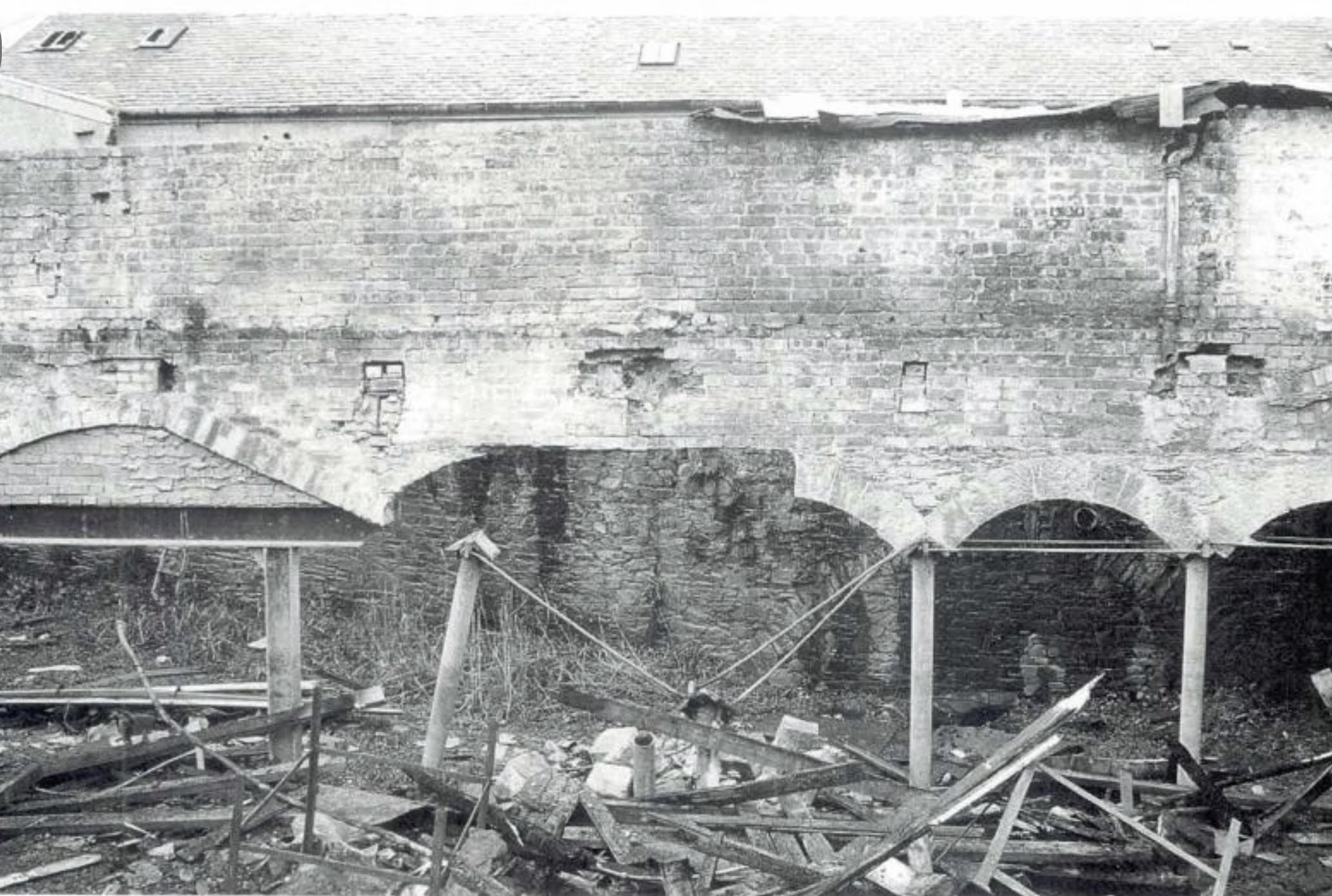
I came across this rather interesting photo, which shows the remains of a partially demolished nineteenth century mill. 


The picture is dominated by a large brick wall, which is suspended above ground level. The original load-path for its support appears to have been an arcade consisting of cast iron columns carried on masonry arches. 

To the left of the image one of the arches has been altered. The profile of its voussoirs has been straightened on one side and the arch infilled with modern brickwork. The infill brickwork is in turn supported on a modern beam and post structure, which is likely formed of hot rolled steelwork.

Below the centre of the wall two of the cast iron columns have been pushed over. The one on the left is clearly visible, while the one on the right is a little harder to pick out. Its head can be detected, because it is still connected to the wrought iron rods that would have been used to resist thrusts at its abutments. To the right of the photo the rods can still be seen linking the remaining iron columns.

It is also evident that the masonry arches which would have been carried by the missing columns have collapsed. It is assumed that rubble, which can be seen at the base of the picture, is what remains of them.

What is of course remarkable is that the brick wall continues to stand. It has found a way of bridging between the steel column on the left and the cast iron column on the right. This is interesting for several reasons.

Since the span is roughly equal to the height of the wall it is reasonable to assume that it has achieved this feat by acting as a deep beam. Were the deep beam made of concrete it would be normal to assess it using a ‘strut and tie’ model. This means imagining a triangular load path in the wall. The two vertices of the triangle form compressive struts, which are sat over the supporting columns, while reinforcement in the base of the wall would complete the triangle by resisting lateral thrusts from the inclined struts. An alternative way of considering this model would be to think of it as a tied arch, as the principle would be similar. Indeed, post failure the residual brickwork appears to have formed a crude arch between the column supports.

In this case there is no concrete and no reinforcement, because the wall is made of brick. Brick is good in compression, which would seem to make either an arch, or compressive struts, a viable load path, however there is no equivalent for the reinforcement, which is required to complete the triangle. 

Brickwork is poor in tension and therefore the base of the wall ought to have failed, however there seems little evidence of distress other than the smaller arches giving way to form a larger, if somewhat makeshift arch.

This means the deep beam must, on this occasion, have a different mechanism for resisting lateral thrust. Two options seem plausible, though one seems more likely than the other. 

It is possible that there are rigid load-resisting structures located just out of picture on either side of the image, however if this were the case then there would be no need for the wrought iron ties, which originally held the column heads together.

It seems more likely that the weight of the brick located above the arch supports is sufficient to divert the arch thrusts back to the vertical i.e. it behaves like heavy bridge abutments. Both headers and stretchers can be seen in the brickwork suggesting that the wall is at least a full brick thick and would therefore be relatively heavy.

Looking carefully at the image there is also evidence of pockets in the brickwork, which would have seated beams in the wall. In fact the remains of an I-shaped steel beam can still be seen embedded on the left hand side. It was presumably easier to cut the beam off at the support than to completely remove it during prior alteration works. This may be relevant because the load carried by the wall must have been reduced. This in turn means the thrust is less.

Since two columns are missing we would ordinarily expect those which remain to take 100% more load. For this reason a reduction in load carried by the wall is of significant benefit to the columns too.

So it would seem that a structure whose intended load-path has been compromised has managed to find an alternative load-path demonstrating rather well that structures will exhaust all possible ways of standing before they collapses.

This does not mean that we would necessarily wish to rely on this load path in the long-term, but nevertheless it is a reminder for engineers that there is more than one way of looking at a problem….in this case an accidental bridge.


Sunday, January 31, 2021

On Howe Trusses Work [yet again]

The benefit of u-frame action


In previous posts we have looked at different forms of truss and how they work. We started with an intrigue about the underlying logic of the Howe Truss and moved on to look at the intricacies of various other forms. Something that may not have been obvious, perhaps until part way through the post immediately prior to this one, is that we have thus far existed in a 2D world, we have not yet looked in the third dimension and considered what happens to trusses out of plane.

The place where this is most obviously important is the top chord. We have discovered already that the top chord is in compression and that failure by compressive buckling is proportional to the square of a member’s length. In the plane of a truss its effective length is relatively short due to the position of the internal chords connected along its length.

Out of plane there is of course no restraint from and therefore the effective length of the top chord is the full length of the truss. The top chord is almost certainly going to buckle. This is a pretty big issue to have overlooked. Fortunately there are several solutions available to solve this particular problem.

In almost all cases trusses come in pairs, for example one either side of a bridge deck. Our first option is therefore to take benefit from the bridge deck, which can be attached to the top chord of both. Since the deck is relatively stiff in plane, sometimes it may even be braced, it will have the capacity to prevent the top truss chords from displacing laterally. They are therefore unable to buckle.

The trouble with this solution is that it is rarely viable in practise. If, for example, our bridge were to span over a motorway, and the deck were located on the truss top chords, one of two scenarios would occur. Either the bottom of the truss would project down into the road below or the whole truss would need to be lifted up into the air meaning that much larger ramps would be needed to get traffic up unto the bridge.

For this reason a better solution is to place the bridge deck on the bottom chords. This, however, reintroduces the problem of top chord buckling. If the trusses are tall enough the possibility exists to introduce a horizontal truss between the two top chords. The purpose of this truss is to resist the out-of-plane loading that results from top chord buckling. It does so by the same means that the vertical trusses resist the loads to which they are subject.The two vertical and one horizontal truss exist in a symbiotic relationship, because the vertical ones can equally resist buckling action in the horizontal truss.


It is also worth noting that if our hypothetical bridge structure is outside it will also be subjected to the full force of the wind and our horizontal truss can, in combination with the bridge deck, be used to resist the wind.

A problem arises when the vertical trusses are not tall enough to permit passage below the horizontal truss. You would not wish to duck as you passed along the bridge. It would of course be possible to increase their height, but this seems an inelegant solution and a waste of material if the trusses need not be so tall. A different approach is needed.

This is the perfect opportunity for u-frame action. U-frame action requires continuity between the vertical chords in the two bridge trusses. This is achieved with horizontal members that connect them beneath the bridge deck. If the connections are stiff enough to resist bending forces then a series of rigid u-shaped structures are formed along the length of the bridge. If the top truss chords then try to move laterally and buckle their vertical chords are able to provide resistance by cantilevering from the horizontal member below the bridge deck. This is known as u-frame action. In this way the bridge trusses remain stable without the need for a horizontal truss. It is a neat solution, which is not obvious to the casual observer, and makes for an elegant bridge with unobstructed views.


Sunday, January 24, 2021

On Howe Trusses Work [again]

Consideration of some additional forms


In my last post I described the ‘deeper magic’ that underlies Howe Trusses by describing the counter intuitive logic, at least to modern engineers, which underlies them. We also referred to a textbook diagram, which included various different families of truss. On that occasion we only looked at those trusses that were necessary to explain the Howe truss. 

In this post I thought it would be useful to revisit the text book diagram, which is reproduced below, and explain some of the remaining trusses.


When a truss is particularly deep, perhaps because the span is large, the gap between bays can become large and the top chord of the truss, which is more heavily loaded than the internal chords, becomes vulnerable to vertical buckling [1]. To prevent this from happening the top chord needs to become thick and heavy. In these circumstances it can make sense to shorten its effective length instead by introducing secondary triangulation [g]. 

Today such trusses are not used much because the additional joints make the structure statically indeterminate, which can result in unwanted secondary stresses, if there are minor defects or errors in the jointing.

The k-truss [h] can be a good alternative when a truss needs to be deep and the verticals are prone to buckle. The jointing remains relatively simple, but the k-shape shortens the effective length of the vertical members allowing them to take up a more slender form.

A further efficiency can be made to the design of long span trusses by taking up the form of the overall bending forces to which they are subject [i]. If the truss bridges a single span it is self evident that the maximum force is in the centre of the span reducing to zero at the supports located at either end. A truss which is deep in the middle and shallow at the ends will therefore use materials more efficiently.

That said there is a disadvantage to this form of truss. As the profile of the truss changes along its length the angle of the internal chords must also change. Near the ends of the truss their angle of inclination becomes quite acute and it is there difficult to form the joint and the member is rather inefficient.

A sensible compromise is therefore to add a web-post at either end. This brings the benefit of matching the overall bending forces while making the internal chords at either end of the truss more practical [j].

There are of course many other permutations of truss design, but between this and my prior post we have outlined some of the key principles that underly many of the most common forms.


[1] we have not yet talked about out of plane buckling. This will be the subject of a further post on the subject of trusses. 


Sunday, January 17, 2021

On Howe Trusses Work

A search for deeper magic


‘"It means," said Aslan, "that though the Witch knew the Deep Magic, there is a magic deeper still which she did not know. Her knowledge goes back only to the dawn of time. But if she could have looked a little further back, into the stillness and the darkness before Time dawned, she would have read there a different incantation”‘ [1]

Trusses are a great way of spanning a long distance; without a web plate they are much lighter than an equivalent beam or girder. Nonetheless not all trusses are equal. There are many different ways that truss chords can be arranged making some more efficient than others. Most arrangements will fall within a family of trusses that share a standard arrangement of chords. Normally structural analysis text books will contain a diagram showing each family stating their names underneath. An example is shown below.


For many years there was something that bugged me about this type of diagram. It wasn’t the diagram per se that bugged me, but rather a particular family known as the Howe truss. This truss bugged me, because it didn’t make sense. I couldn’t work out why on earth Mr Howe, whoever he was, had come up with the design that he did. It is just so inefficient, or so it seemed. It turns out, however, that Mr Howe was right and I was wrong. It turns out that he knew deeper magic than I did. In this metaphor that made me the Witch, which I didn’t like very much!

This post is therefore about truss design and about Howe I learned some ‘deeper magic’.

Before we get to my mistake we need to learn something about how trusses work, which will help you understand why I made a mistake in the first place. It will also help you appreciate the existence of deeper magic and how clever Mr Howe was.

In the beginning iron and steel bridges were quite complex, but progressed to simpler arrangements over time. The progression has an intuitive feel to it. At the outset engineers were perhaps thinking about how to lighten the web of a beam or girder and decided to do so by creating a trellis arrangement [a]. For this type of truss there would have been great expense making all the joints and it would have no doubt taken a long time to fabricate. It would also have been clear that being highly redundant it could not be designed by normal static methods.

Engineers would soon have been realised that more economic trusses could be made if the number of internal chords could be reduced. This would make them lighter; they would require fewer joints; and they would be simpler to analyse.

The Bollman truss [b] was designed with pairs of diagonal members extending from the supports at either end to intermediate points on the span. It has an interesting aesthetic, but has several drawbacks. Firstly, if load is applied at a node point only the pair of diagonals connected to that node is mobilised to carry the load; all the others become redundant. A more economic structure would utilise all the chords simultaneously. A second disadvantage is that, except for the middle set, pairs of diagonals are necessarily inclined at different angles. This means that they must carry different magnitudes of load and consequently rather unhelpful secondary stresses are induced. It turns out that diagonals are better suited to being set at a regular angle of inclination, perhaps somewhere between 45 and 60 degrees.

The Warren truss [c] is a good example of this. It has a simple arrangement of diagonals arranged in the shape of equilateral triangles. It minimises the number of members and joints, and what is more, all members are the same length. It is an efficient truss that is simple to fabricate and is statically determinate [easy to analyse]. What is not to like?

Nevertheless, for all its advantages the Warren Truss does have a disadvantage and we can therefore improve on its design. That disadvantage comes from a consideration of the type and distribution of forces its chords must carry. 

If we imagine for a moment that we are dealing with a beam and not a truss a useful analogy can be made. As the truss takes up load and starts to bend the top chord shortens and the bottom one lengthens. There is therefore compression at the top and tension at the bottom.

The internal chords, which must transfer load between the upper and lower chords behave differently. Those which point towards the supports shorten and are in compression; those which point towards the centre of the span lengthen and are in tension.

There is of course a difference between tension and compression forces. Members that are in compression are prone to buckle in the middle while tension members are not. Since the buckling capacity of compression members is proportional to the square of their length there is a distinct advantage to being shorter. 

This brings us nicely to the Pratt truss [d], whose compression members are arranged vertically. Since the verticals are necessarily shorter than the tensioned diagonals this is a highly efficient form of truss, which recognises the type of loads each member carries.

Observant readers will no doubt have foreseen what comes next. The Howe truss [e] is a complete reversal of the Pratt truss. The tension members are now arranged vertically and the compression members diagonally i.e. the longest members are in compression. If you think this doesn’t make sense you are just like I was and don’t appreciate the deeper magic involved. 

There are of course some other truss families in our diagram, but we are going to leave those for another time so that we can concentrate on the mysterious Howe Truss. In order to get to the bottom of the conundrum we need, like Aslan, to go back in time.

Perhaps the first trusses were timber roof trusses. Unlike trusses of iron and steel they would have started simple and became more complex over time. A pitched roof would have been an advantage to early builders, as it is today, because it encourages water to flow away from the building; it is less likely to develop a leak. 

It is self-evident that inclined rafters are required to create the pitch. This in turn implies rafters, which lean against each other and therefore tend to spread at their bases. The associated spreading force is rather unhelpful to the supporting walls. A horizontal thrust applied at their head will of course make them unstable and push them over. To stop this from happening a horizontal tie is added forming the most basic form of triangular truss.


With the success of this form it stands to reason that the designer will soon want to bridge a bigger span. This would have brought a new effect to the designers attention. With increased span the tie beam would begin to sag under its own self weight. To prevent this from happening the solution would be to suspend the middle of the tie beam from the rafters using a new tie member called a King Post. If the spans increased again the rafters would surely begin to sag too. It therefore becomes necessary to prop them with struts supported on the tie beam. To prevent the tie beam from being bent the struts would be joined at the same point the king post is connected, thereby transferring the propping load back into the rafters in tension.

The next development would be to minimise the length of our new struts to stop them from buckling. This can be done by making them perpendicular to the rafters. The trouble with this arrangement is that they now bear on the bottom ties at a distance from the King Post and thus bending is reintroduced to the system. For obvious reasons this is undesirable. The solution is to replace the King post with two tension ties, which join the struts to the apex of the rafters, thus eliminating tension. 

We have nearly reached the end of our detour into timber roof trusses and are almost ready to return to the Howe Truss. Before we get there we must learn one more thing about timber roof trusses. When timber members are in compression they are squashed together and load is conveyed at the joint in bearing. This allows relatively high loads to be transferred. Conversely, when two members are in tension they require timber pegs inserted between them to hold them together. In this case all of the load is transferred through the pegs alone, which are much smaller than the overall member size and are not terribly strong. For this reason tension joints are the weak link in the system.

To overcome this problem engineers began to use wrought iron straps to transfer loads at tension joints. It could not have been long before it was realised that the tension members themselves could take the form of wrought iron rods. The advantage being that they could be inserted through the timber chords and clamped tight with large washer plates.

This results in a hybrid structure, which is very efficient, because in a time when iron was expensive and difficult to produce, it uses relatively cheap timber to carry compressive loads and iron to form the tension members and joints.

This is the key to unlocking the mysterious Howe Truss. The thing which structural analysis, text books never tell you is that the vertical members are wrought iron or steel and the diagonals are in timber. They also don’t tell you that the verticals are tightened at the fixings until they carry a pre-stress, which keeps them permanently in tension. By doing so the compression members are clamped tightly together. The timber members are stocky compared to the slender ties and are therefore not vulnerable to buckling.

This is where that deeper magic begins. The logic which governs the design of modern steel trusses does not apply to older trusses made of timber, due to the limited capacity of timber joints in tension and the cost of making iron.


That said there is something else that you need to know. William Howe was an American engineer who invented his eponymous truss for use in the construction of railroad bridges. In the vast spaces of the United States it stands to reason that it would have been more efficient to cut timbers from trees near to the site of a planned bridge rather than having to transport all the iron members from a fabrication yard.

It all makes sense now, Mr Howe was in fact a rather clever man.

Before I finish this post there is one further thing that I need to explain. Most archive images of Howe trusses have diagonal members in two directions rather than one, they don’t actually look like those found in structural analysis text books. This tells me that their authors are only familiar with the theoretical form of the truss and not how they were made or what they were used for.

The reason for the additional chords is also related to the construction of railroad bridges. Howe realised that as a heavy steam locomotive passed over one of his bridges it would experience uneven loading and this could potentially cause load reversal in some of the chords. The additional members were used to ensure that there were always members acting in compression. 


[1] chapter 15, ‘The Lion the Witch and the Wardrobe’ by C S Lewis.


Sunday, October 25, 2020

On Lies, Damned Lies & Statistics

Why statistics are actually quite useful


“Figures often beguile me,” wrote the American Author Mark Twain, “particularly when I have the arranging of them myself; in which case the remark attributed to Disraeli would often apply with justice and force: ‘There are three kinds of lies: lies, damned lies, and statistics’”.

It is somewhat ironic that a sentence about degrees of falsehood appears to contain one, though most likely unintended. The earliest known appearance of the phrase attributed to British Prime Minister Benjamin Disraeli was in fact after his death.

Never-the-less it is a pithy phrase, which has remained in common parlance, most likely due to the habit politicians have for selectively marshalling statistics in support of their policy decisions. The idea being to give them a veneer of mathematical rigour.

This habit led, over time, to an acute public distrust of Government Statistics; so acute that in 2007 Parliament passed an act which made the Office for National Statistics independent of Government.

This is why I fear that this, my attempt to show why statistics matter and why they are in fact very reliable, could backfire spectacularly.

In order to make that case we must turn to the subject of how we know that a structure designed by an engineer will not fall down. It is of course self evident that some structures do fail, however before explaining why that is we must first explain why most of the time they don’t. We are not here talking about situations where a design has been created in error; that may not be fairly attributed to statistics.

It would of course be possible to build a structure and then test it for the desired load, however this is not entirely practical. If the structure fails to pass then there will have been a rather significant waste of time and materials to build it. Something more reliable is therefore required. 

A second option would be to proof test each of the components that are used to fabricate a given structure. This was in fact the method that was sometimes used, particularly for large or novel civil engineering structures. This has the advantage of not destroying the whole structure if a test specimen fails.

That said, it is still not a terribly efficient method manufacture, due to the time and expense of the testing regime, which is bespoke to the structure being constructed and cannot be re-used for different arrangements. 

It might be possible to test a model of the whole structure, however this approach has many difficulties. Firstly, most structural effects do not scale linearly i.e. behaviour at small scale is different to that at large scale, therefore in all but the simplest cases the model structure will not represent real behaviour at full scale[1]. Secondly, if we solved the scaling problem we still could not be sure that the actual model would behave as the real structure, because we have not tested the actual structure. This brings us back to the point we started.

What is needed is a reliable method of predicting the point of failure irrespective of whether a structure is a test model or the real thing.

Supposing that we required iron chain links, which are to be used in a suspension bridge, to carry 4 tonnes of load. If we tested a link and found that it could resist 1 tonne then we might conclude that 4 links are required. 


The difficulty is that if we did another test we are likely to get a different answer; perhaps less than 1 tonne; perhaps more. We could conduct 10 tests and each time we would very likely get a different answer. The reason for this is the presence of small, perhaps imperceptible, differences in the manufacturing of each one, which are impossible to eliminate completely, even with modern technology. 

The question therefore becomes, which of the test results should be used for the design?

Some would say the average figure should be used, however it does not take long to work out why this cannot be correct. It is self-evident that half of the links will have a capacity that is less than assumed in the design. That cannot possibly be a safe outcome.

Another idea would be to adopt the lowest value. Surely by definition this option must produce a safe, if cautious, result. If, however, we think a bit further we might consider how we know that any of the10 tests we have conducted thus far represent the lowest test result that we could get. After all, what if we conduct test number 11 and the result turns out to be lower than the lowest we had obtained thus far?

This turns out to be a bigger problem than initially seemed to be the case, for how do we know that test 12 won’t be worse still? The question appears to recur infinitely. We need a better answer and that is where statistics comes in.

All materials, or components for that matter, are imbued with a curious property that is wholly reliable, completely unchangeable, and is it would seem, an intrinsic property of nature itself. 

Despite its universal applicability, it is a deceptively simple concept to demonstrate. Supposing we started by plotting a bar chart [histogram] showing the distribution of our results. Along the bottom axis we plot the capacity of the links we have tested and on the vertical axis we plot the number of links that achieve a given capacity.

As we plot the test results we will find that they start to cluster around the average with fewer results corresponding to capacities either much greater or much less than the average.

With still more tests the cluster will start to develop into a recognisable pattern resembling the shape of a bell, where the top of the bell is located at the average value. It will soon become clear that no matter how many new results are added the overall pattern of the results does not change; the bell is there to stay.  


For obvious reasons a curved line which bounds all of the plotted results is called a ‘bell curve’. Johann Carl Friedrich Gauss was the first person to describe such curves mathematically, which is why they are also known as Gaussian distributions.

As soon as it is possible to describe the curve mathematically we need only a limited number of test results to do so. Once we have done this mathematics also gives us the ability to predict the probability of a given capacity being exceeded, or in other words we can predict how likely the material or component is to fail. All we then need to do is decide what probability of failure is acceptable.

This is an interesting question for several reasons. Firstly, it is not entirely an engineering question. It requires a decision to be made about what level of failure is tolerable. This is unquestionably influenced by public perception of what ought to be. Public opinion can be a fickle thing, which can often be contradictory, especially when emotion is involved. 

For example, if something has been done a particular way for many years the public are loath to have it changed or restricted in any way. You are bound to hear someone say “it has always been done this way and it has performed been perfectly well. Why do you feel the need to change it.”

In reality this is often not the case. What someone thinks represents the way something has always been done often turns out to be nothing of the sort. It is in fact an imitation of what has been done previously. In reality it has been changed over the years in many small imperceptible ways, but the cumulative effect of those changes has not always been appreciated and may one day be the cause of failure.

Conversely if there has already been a major failure, particularly one that has caused the loss of life, then the public demand will be for immediate change and for someone to be held to account. It will be said “how did nobody foresee that this could happen? There must be either negligence of incompetence. This cannot be allowed to happen again; something must be done.”

In this way public opinion is largely based on momentum. We do not wish things to change until there has been a rude awakening that forces us to re-think and then we must have change and the status quo will not do.

One of the ways that engineers think about this problem is to consider both the likelihood and the consequences of failure i.e. how probable is it for something to go wrong and what would happen if it did? 

It is obvious that the failure of a nuclear power plant or a hydroelectric dam would have consequences far greater than the failure of a roof purlin in an agricultural barn. Quite reasonably one might wish the former examples to be less likely than the latter.

It is also obvious that it is not economically viable to design barns like power stations. Nor is it aesthetically desirable to design barns that way. It may seem curious to discuss aesthetics in this context, however humans do place a value in art and culture. We do not wish to live in homes that look like nuclear bunkers and we rarely purchase a car based wholly on the results of safety testing. Aesthetics are important to us.

Perhaps a more subtle example of likelihood and consequence is to re-consider our bridge links. Since we have determined that more than one link is required. It seems improbable that all the links would be sub-standard, which opens the intriguing possibility that the systemic probability of failure may be quite different to the probability of an individual component failing. This would of course rely on the remaining links being capable of sustaining extra load due to the failure of their neighbour. This introduces the concepts of redundancy and margins of safety, but these are for a different blog post.

For now we are simply concerned with the bell curve and its ability to predict the probability of failure in a reliable way, based on a finite set of test results. It gives engineers the ability and the freedom to make reasoned judgements about cause and effect, however it does not provide engineers with an answer to the question of what an acceptable failure is.

This is of course the reason why some failures do happen; it is simply because they have been deemed to be acceptable, perhaps on the basis of a more robust structure being too expensive when compared to the perceived benefits. However, as we have learned, what is acceptable is not a fixed thing and may change with public perception.

A good example might be the failure of a flood prevention barrier shortly after it is completed. Presumably people chose to live close to the water, because they like the view and they do not wish to live behind a large wall that obscures said view. 

That being said, those same residents, when flooded, are not particularly interested in hearing that given the magnitude of flood event that has occurred failure of the barrier had been judged tolerable.

Statistics are therefore an eminently useful thing, which can inform our decisions, but cannot make tough choices on our behalf. We must decide what our appetite for risk is based on many subjective factors. Whether they know it or not this is the dilemma faced by all politicians and is probably what tempts some of them to misuse statistics. Like anyone else they do not wish to be held responsible for a decision that might be criticised in retrospect. They would rather believe that statistics can absolve them of that responsibility.

Unfortunately statistics can only ever tell us the probability of an event and not whether said event is good or bad. Perhaps Mark Twain should have said:

"There are three kinds of lies: lies, damned lies, and self-deception”.


[1]I am aware that there was a period in time where testing of models was adopted, but this is a rather complicated subject involving some interesting mathematics and is perhaps a subject for another time


On Ice Shelf Cracking

Tension Cracks in the Brunt Ice Shelf Yesterday the BBC news website published images showing a large section of the Brunt ice shelf in Ant...