Showing posts with label arches. Show all posts

Sunday, June 13, 2021

On Ice Arches

Understanding ice flows in the Nares Strait

Today an article on the BBC website caught my interest, but perhaps not for reason the author intended. The article describe the premature disintegration of an ice arch that bridges between Greenland and Ellesmere Island. The arch had blocked the so called Nares Strait, much like the damming of a river, thus preventing the southern migration of the ice flow. Viewed from space the arch is spectacular. The images below show before and after disintegration.


The point of the BBC article was to highlight the effect of a changing climate and what might result from increased ice flow. I have no interest in discussing this; it doesn’t remotely fall within my expertise and I don’t have anything new or novel to bring to the topic. 

Instead, what initially crossed my mind was whether this, and similar structures, I assume other examples must exist, might be the largest arches on the planet. I have no idea whether this is the case or not, but one has to think that they must be contenders.

My mind then turned to the question of why such arches form and whether they were in fact true arches at all. As it turns out I think the two questions could be linked. Not that I really know anything about this subject either, but I do at least feel more comfortable to speculate on the basis of structural principals.

The ‘before’ photo shows the ice flow firmly interlocked with the coast of each land mass. The interlocking extends over a distance, which exceeds the width of the strait and that seems significant to me. The reason I view this as important is that a member whose depth exceeds half its width fits the definition of a deep beam. A deep beam is one that is of sufficient depth that its behaviour is no longer governed by bending effects. I therefore wondered whether what we actually had was a deep beam rather than an arch. That gave me cause to think about how a deep beam actually works. It was this that lead me to postulate how, and I suppose why, an ice arch might form.

The effective depth of a deep beam is roughly equal to its span. It follows that there is little load resisting contribution from the ice flow beyond that point. Normally within a deep beam’s effective depth the stresses behave a bit like an imaginary tied arch with a compression zone at the top, which pushes outwards towards the sides. There must also be a corresponding tension zone at the bottom of the beam, the tie, which prevents the internal ‘arch’ from spreading and tension cracks from forming.

The trouble is that this isn’t what we see in the satellite image. The tension zone is completely missing, leaving the observed arch profile at the base of the ice flow. The obvious reason for this would be that ice is an anisotropic material; it is strong in compression, but has little or no strength on tension. Self-evidently, since there is is an absence of tension capacity, the section of ice exposed to tension has, presumably, cracked and floated away prior to the picture being taken, thus leaving behind an arch profile.

That said, while this may explain the formation of an arch profile it can’t be the whole story. If there is no tie stopping the ice arch from spreading why hasn’t the arch itself collapsed? The answer must be that the land mass on either side of the ice flow provide strong buttresses, which contain and resist the outward thrusts. 

This, however, still doesn’t entirely explain what is going on, because if the buttresses are secure then no tension can be present in the ice flow and if that is so why did the bottom of the ice flow fall out.

Assuming the buttress theory to be correct I can think of several potential mechanisms, but I am not sure which, if any, are contributory.

My first thought would be that perhaps the ice formation takes time to interlock with the land mass and the arch is able to spread while it is still forming. Perhaps during the formation process ice at the land interface cracks and breaks, as the ice flow moves south only becoming solid and immovable as it is slowly pushed and squashed into all the available gaps. Perhaps there is also undulation in the ground and some of the ice rides up over the shallow flat parts until it is is resisted by projections.

Maybe, despite the appearance of static resistance, even the arch is moving slowly southwards and the buttresses gradually shift and adjust. Not enough for the arch to fail, but enough for tension cracks to form at the base of the ice flow.

These would seem, at least to me, plausible explanations for the formation of an arched profile. The question is whether what we are actually seeing is in fact a true arch. We had been considering the possibility of deep beam behaviour, but have, without noticing, slipped back into describing the structure as an arch.

I think it would be just as correct to view the structure as a buttressed deep beam with the effect of rigid coastlines replacing the beam’s tension zone. Though this is perhaps an unusual description I happen to think it is a better description than a true arch. I have three reasons for this.

Firstly, I don’t think the ‘arch profile’ forms without the ice flow first trying to behave as a deep beam. Secondly, due to the re-distribution of forces within the depth of the structure, caused by the buttresses adjusting I don’t think you can avoid the conclusion that stresses are set up across the full width and effective depth of the ice flow. Thirdly, using classical arch theory, which has been discussed in prior posts about masonry arches, I don’t think you could stop the thrust line leaking out of the optimal arch shape due to the depth of the structure and the behaviour of the abutments...actually I’m not sure that’s not just another way of stating reason two.

So, that would be my answer. I think that the base of the ice flow has the appearance of an arch, but is in fact a buttressed deep beam, or maybe that’s just a speculative folly on my part. 

One notable point is that I have offered no comment on the ‘after’ picture. I guess that’s because I wanted to talk about the apparent arch itself, it seems obvious that it would start to fail if the ice melts. Maybe the ‘after’ scenario shows what the ice flow looks like as the structure is forming and the ice is being squashed together. I have no idea if that is true, but aesthetically I am drawn to the idea of a circular process. Perhaps if the temperature is lower at higher latitudes a new wider ‘arch’ will form further north.


Sunday, June 6, 2021

On Devorgilla Bridge

Some Characteristics of Stone Bridges 

Last summer I took a camping trip with friends and family to the Scottish borders. We happened to visit the town of Dumfries, which straddles the river Nith and has a number of interesting bridges. One of these is known as the Devorigilla Bridge, although in reality the name applies to a succession of bridges dating to circa 1270. The first of these was built by, or at least funded by, Lady Dergovilla, the mother of John Balliol, who became king of Scotland in 1292. Dergovilla was also responsible for founding Balliol college in Oxford. 


I new of John Balliol, he was king at the outset of Scotland’s War of independence, and I knew of Balliol college, though I had not until this point linked them together. I did not know anything of Devorigilla Bridge, however by observation it was clear to me that it was certainly old and had undergone several periods of change …. and that was interesting.

The bridge spans the river with six masonry arches, which appear to be of equal size. The masonry is generally a red sandstone, which is squared and coursed, although the parapets are grey rubble, which is random in some locations and coursed in others.

There are notable features at either end of the bridge, which appear to provide some clues about its past. The first arch, which springs from the western river bank, is pointed while the five remaining arches are semi-circular. On the eastern bank there is a staircase, which descends from the bridge to current street level.

Although semi-circular arches were used by the Romans, and therefore predate later Gothic [pointed] arches, the change from romanesque to gothic happened in the 13th century prior to most stone bridges in Scotland being built. Romanesque designs returned around the 16th century during the renaissance period. 

This implied that the single gothic arch was much older than the five romanesque ones. Anecdotally this would seem correct, as we might expect a bridge to be re-built after being overwhelmed and destroyed by flood waters. It seems more plausible that the single arch located next to the river bank would survive intact rather than those located in the middle of the river where the flow is greatest.

On the opposite bank a staircase to exit the bridge seemed like an odd feature. While today the bridge carries only foot traffic, and vehicles pass over more modern bridges, in its heyday Devorgilla bridge would surely have carried carts and wagons. It must be likely that tolls on goods would have been collected to help fund the bridge. Why then would the bridge have stairs at one end? 


The conclusion I drew is that the bridge was not constructed this way. There must have been at least one additional span, which was for some reason truncated or removed at a later date. It seemed to me that the likely period when this might have happened would be the 17th century. My logic for this was the distinct parapet stonework, which I have already mentioned in passing. 

Bridges before the 17th century tended to have coursed, well-squared stones, whereas for a 100 years or so afterwards courser rubble masonry was often used. If then the end of the bridge had to be re-modelled, due to the end span being truncated, the works would necessarily need to include the parapet. The opportunity may then have been taken to look at the parapet in general. This work would then be reflected in the courser stonework that can be seen in the masonry today.

Having made what seemed to me some reasonable engineering observations I wanted to know more about the history of the bridge and I was therefore delighted to find a small plaque located near to the bridge on the western bank of the river. The plaque confirmed some of my suspicions.

The bridge was built in 1431 to replace the first wooden structure erected by Lady Devorgilla, but was largely destroyed in the 1620’s resulting in a nine arch bridge being built to replace the 1431 version. 

It also noted that in 1790 the Buccleuch Street bridge was constructed, which currently carries road traffic to the north, and has itself undergone alterations. In order to build the Buccleuch Street bridge land on the eastern bank was built up to meet it. This action would have required the Devorgilla bridge to be truncated.

1790 is probably a bit late for the general remodelling of the parapets, although some works would have been required where the steps were created. It certainly looks like more work has been done to the parapets above the final two arches.

It follows that while some of my conclusions remain speculative, their broad outline seem to be borne out by the official history. My curiosity has therefore been sufficiently satisfied to move on to something new, as my interest lies in observation of the structure rather than pure historical research. I shall leave it to others with greater historical interest to work out the details and show where I have gone wrong….not too much I hope.


Sunday, May 30, 2021

On Horseshoe Arches

Why use a horseshoe arch?

Historically many types of arch have been used to construct buildings and bridges. The underlying reasons for adopting each of the main types is normally relatively clear, however in the case of the horseshoe arch this is not so. The Romans predominately used the semi-circular arch. It has a geometrically simple form, which is straightforward to understand and straightforward to construct. It is perhaps the reference point for comparison with other forms.

The segmental arch is much flatter and is often used for constructing bridges. It is less efficient structurally than a semi-circular arch, in the sense that the lateral thrusts are greater. This means that larger abutments are required. The reason for choosing a segmental arch is to avoid creating steep inclines for the ramps onto a bridge. This is the reason heavy abutments are a price worth paying.

Pointed arches are characteristic of gothic architecture. There are very good reasons for adopting them. The first reason is geometrical. The rise of semi-circular arches varies with the span. Pointed arches can have the same rise for different spans. This is a useful trait when vaulting a gothic cathedral. A second benefit to pointed arches is that the lateral thrust at the abutments is less than for a semi-circular arch of the same span. This is also important for framing gothic cathedrals which are propped by delicate flying buttresses. Another reason, which is often sighted, though of little importance from a structural perspective, is that pointed arches can be used to create a higher ceiling. This enabled more light in the building and was viewed as being symbolic in a cathedral structure, because it was closer to God.


Now, returning to the archetype with which we began, the horseshoe or moorish arch. A google search will reveal that the purpose of this form is not at all clear. Even academic writings seem to be rather woolly on the topic. Explanations, particularly in architectural papers, seem to focus on somewhat subjective views about symbolic meaning and many of the structural explanations are far from compelling. 

Some point to the provision of a wider seating, which will reduce the bearing stress at the base. This is of course true, however since the compressive stresses in masonry structures are low to begin with its not really a material observation. 

Others say that horseshoe arches can be built without centring, as apposed to a semi-circular arch, which cannot. This argument makes no sense at all, at least to me. I do not see any property of a horseshoe arch relative to a semi-circular arch that would make that so.

There is a view, which seems to make sense if the horseshoe is seen as an intermediary between semi-circular and pointed arches, that the horseshoe provides a way of increasing the height of a space. It is self-evidently a taller structure than a semi-circular arch of the same span and, prior to the pointed arch, it would certainly be a good way to achieve a more spacious building interior with greater opportunity for light to penetrate.

One might also argue that the horseshoe is simply an aesthetic choice that was favoured by Moorish designers. This explanation is not terribly satisfactory; it would be disappointing if the traditional Roman semi-circle was replaced with a horseshoe just because it looked nice. I think there is more to it than that.

Analysis of a horseshoe arch with the same span as a semi-circular or segmental arch will show that it has a lower horizontal thrust at the base than either of the other two options. This is clearly an advantage, because the abutments can therefore be smaller. That said in order to re-directed thrust from horizontal to vertical the upper part of the arch must resist bending forces, which could cause buckling if the arch is too thin. 

An example of this form of failure occurred in 2004 when the concrete structure of the newly completed terminal 2E at Charles de Gaul airport collapsed killing 4 people.

The tendency to buckle can be resisted if the arch is confined on either side. Indeed, in every example I have seen of masonry horseshoes they are either confined by spandrels or are balanced by other arches pushing with an equal force in the opposite direction. Of course potential buckling forces were reduced by the subsequent development of the pointed arch. 

Nevertheless, if the upper part a horseshoe arch has sufficient bending capacity, in the case of modern materials, or is sufficiently confined, in the case of masonry, then the resulting thrusts at the base of the arch are somewhat reduced and this is a distinct advantage.

One of the reasons I think that Moorish designers knew what they were doing and were thinking about structural load paths is evident in the detail of their construction. It is noticeable that the portion of the arch below the semi-circle is invariably formed of a single piece of stone or from a series of specially shaped blocks that do not follow the standard format of the voussoirs above. This is essentially to ensure that the angle of the joints all point inwards thus making it easier to construct, because the stones cannot slip outwards before the arch has been completed. It likely also makes the arch less prone to fail due to lateral thrust in the permanent case.


In summary I rather suspect that the horseshoe arch was originally developed as a means of amending a semi-circular arch in order to create a taller space. It seems like a logical step to simply use a larger proportion of the circle. Through experimentation, probably with single arches to begin with, the behaviour of such structures started to be understood, which ultimately led to some of the rather impressive arcades and other structures that came to characterise Islamic Architecture to this day.

This is of course a speculation on my part, as I have not completed a detailed historical study of horseshoe arches. I trust however that being based on the structural properties of horseshoe arches, it has at least some interest and merit. I am certainly no less impressed by the clever use of horseshoe arches than I am the semi-circular Roman arches that preceded them or the pointed gothic arches that followed. I also have no doubt that the Moorish legacy of horseshoe arches in Spain would have been an important influence on medieval architecture in Europe thereafter.


Sunday, May 2, 2021

On Gothic Cathedrals

How tracery works


When it comes to gothic cathedrals most people tend to think of flying buttresses. There is of course no doubt that flying buttresses were a tremendous invention and are indeed an important part of gothic architecture.

Nevertheless, while flying buttresses are rather clever devices that provide a clear load-path, the thing that always leaves me astonished is how gothic tracery works. Even when you know its secret the slenderness of gothic tracery still appears to defy the laws of physics. Perhaps, one of the best examples is to be found at Gloucester Cathedral.

The stained glass window at the end of the Chancel is reported to be the size of a tennis court, and it fills almost the entire gable. The stonework seems impossibly thin, how on earth do the mullions manage to span from floor to roof? 


Before we answer that question we are first going to take a diversion into my childhood. Every year, after Christmas, one of the things that we liked to do as a family was settle down in from of the television to watch the World’s Strongest Man competition, which back then was televised on the BBC. We would cheer on Geoff Capes, who won the competition on several occasions, and was always in with a chance.

One of the delights of the competition, which has been lost in its modern incarnation, was the nature of the games in which the competitors were required to compete. While truck pulling and car lifting has been retained, but back then there was arm wrestling, bending iron bars behind the neck, balancing weights on your head and other such fun. Another of the lost games was brick lifting. If you have never seen brick lifting before its not as straightforward as it sounds. The bricks are laid out horizontally on table and are lifted by stretching out the arms and grabbing the stack at either end. It is self evident that simply holding the two end bricks and lifting would not work. There is nothing joining the bricks together and therefore gravity will keep them firmly planted on the table. To lift the bricks it is first necessary to apply axial pressure to the stack in order to generate friction between the bricks. The magnitude of the frictional force must exceed the force of gravity in order that the strongman can lift the stack without the bricks falling out. 

It is also important to maintain the axial force directly through the centre of the bricks to prevent an unstable hinge from forming. This is harder to do than it might seem because while the arms are clamping they are also required to be lifting. You can see in the image below Geoff Capes’ right arm has moved slightly forward and a hinge has already started to form. It will not be long before the bricks experience a rapid increase in their entropy!


This may have seemed like an odd digression from gothic cathedrals, however it is nonetheless a relevant digression, because it illustrates the principle of prestress that is at work in window tracery. In the case of brick lifting the prestress, which is applied to the bricks before they can be lifted, is provided by the strongman. It is a far greater test of his strength than the actual weight of the bricks themselves. For as long as he maintains compressive force in the stack of bricks it will continue to bridge between his two hands. Since the dominant behaviour is compression the load-path he has created is actually that of a flat arch.

We can apply the same principle to window tracery by turning the problem on its side. But before we do this let us considered the case without prestress. If we imagine the stone mullions as a tall stacks of bricks spanning between the floor and roof it would be rather easy for the wind to simple blow them over. The reason for this is because masonry can resist compression, but not tension. When the wind blows on the window load is transferred from the glass into the stone. The stone begins to bend causing it to take up a curved profile. The windward side of the curve is squashed and is therefore in compression, while the leeward side is stretched and is in tension. Of course masonry cannot resist tension and therefore the masonry fails. 

It follows that the purpose of compressive prestress in window tracery is to overcome the tensile forces that wish to cause bending in the stonework. Providing the compressive stress in the mullions exceed the tensile stresses generated by the wind they will remain stable and can arch from top to bottom. The obvious next question is where the prestress comes from? 

The answer is both simple and clever. Medieval masons simply built some rather heavy masonry above tracery windows demonstrating that they understood exactly what the load-path was. In the example above at Gloucester Cathedral the head of the primary mullions have cleverly been bent to the form of pointed arches and are actually supporting part of the roof, as well as masonry above.

This load path does of course have an important implication that is not necessarily evident straight away. Arches produce lateral thrusts, which must be resisted or they will collapse.

In the example above there is one large arch, which spans the chancel and two subordinate arches that fall within the larger arch. It is also possible to divide the larger arch into three parts; a central arch bridging the two internal mullions with buttresses either side, which transfer load into the two outer mullions. In reality the complete load-path is a combination of the two descriptions and it ensures that there is sufficient compressive load in each mullion.

If we begin with the two subordinate arches it is clear that the thrusts, which push towards the middle of the window are balanced against each other. It is no accident that the heaviest transom in the window extends from the base of each arch and joins them together.

It is also not an accident that the outward thrust from the large arch and the subordinate arches occur in the same place, though the method of resistance is not obvious from inside the chancel.

The key is of course the use of heavy buttresses on the outside of the chancel and that brings us back nicely to where we started, the humble buttress and its more elaborate cousin the flying buttress, which we will tackle in a different post.

Notwithstanding all of the above the ability of gothic tracery to resist all that nature can throw at it still amazes me!


Sunday, April 4, 2021

On Canaletto & Bridges

Tangent & Radial Trussing


The eighteenth century painter Canaletto was well known for his Venetian paintings, many of which were commissioned by British Patrons. This gave him a reason to move to the UK when war broke out.

One of his commissions, painted during his stay in the UK, is ‘A View of Walton Bridge’. The painting is interesting, not because of Canaletto’s skill in depicting the British weather, nor is it because Canaletto doctored the scene by omitting the masonry viaducts leading up to the bridge. Rather it is the nature of the bridge itself. 


At first sight Walton Bridge appears to be a traditional arch structure, however it is in fact a fine example of the tangent and radial truss. The main span was reported to be 130 feet with two side arches of 44 feet. Sadly, the bridge is no longer in existence, due to timber decay.

Tangent and radial trusses are special, because they take up the form of an arch using only straight members. A simpler example, known as the “Mathematical Bridge’, still exists at the University of Cambridge. 


As the name suggests the primary structural members are arranged at tangents to an imaginary circle, thus giving the appearance of an arch. The radial members are aligned perpendicular to the imaginary circle and would, if extended, meet at its centre.

The form is also interesting because the tangential members, which spring from the abutments, are predominantly compression members, while the the radial members predominantly resist tension. Most articles written about ‘Mathematical Bridge’, or at least the ones I have seen, note that this pattern of tension and compression are an elegant visual representation of the forces within an arch. It seems to me that while oft repeated this observation is not strictly true.

A true arch is a pure compression structure where the line of thrust is contained within its depth. Many arches, including most classical and medieval examples, are not actually true arches, they are in fact spandrel arches. Spandrel arches are characterised by an infill [spandrel] structure located above the true arch. If the infill is of sufficiently depth then the line of thrust can move outside the true arch and load can be conveyed within the spandrel. At a certain point the stresses in the spandrel become more akin to those found in a beam and the arch becomes nothing more than an ornamental soffit to the spandrel. Something like this phenomenon is demonstrated in an earlier post titled ‘On Accidental Bridges’.

It follows that tangent and radial trusses are a better depiction of the forces in a spandrel arch than they are a true arch. The tangential members join with the top chord to convey compressive stress, while the radial members combine with the bottom chord to convey tension. Based on this the arrangement would be more efficient if the radial members were in fact not radial, but were instead arranged perpendicular to the tangential members i.e. if their angle of inclination were defined by the stress pattern rather than the centre of an imaginary circle.

Perhaps the reason for using radial members was to avoid a structure with more complex geometry and more awkward jointing, however there are also several other considerations. 

Firstly the radials must provide restraint to the top chord of the truss so that it does not buckle. They do this by generating u-shape action in combination with members below the bridge deck[1]. Secondly, they form a useful part of the balustrade, which would be less effective were they located at a steeper angle.

Before we finish it is also worth noting that tangent and radial trusses were commonly used as centring [temporary support] for masonry arch bridges while they were being built.

One such example was Westminster Bridge in London. We know tangent and radial trusses were used, because the original drawings have been preserved. That little detail didn’t bother Canaletto, who once again used artistic licence when framing a view of London in his painting ‘London: Seen through an Arch of Westminster Bridge’. The timber centring is clearly not formed of tangent and radial trusses. Perhaps Canaletto judged that the elegant structural form would detract from the view he wanted to paint and therefore substituted something more prosaic. At least that’s what I like to think. 


[1] An earlier post titled ‘On Howe Trusses Work [yet again]’ describes u-frame action in more detail.


Sunday, February 14, 2021

On Accidental Bridges

The robustness of brick walls


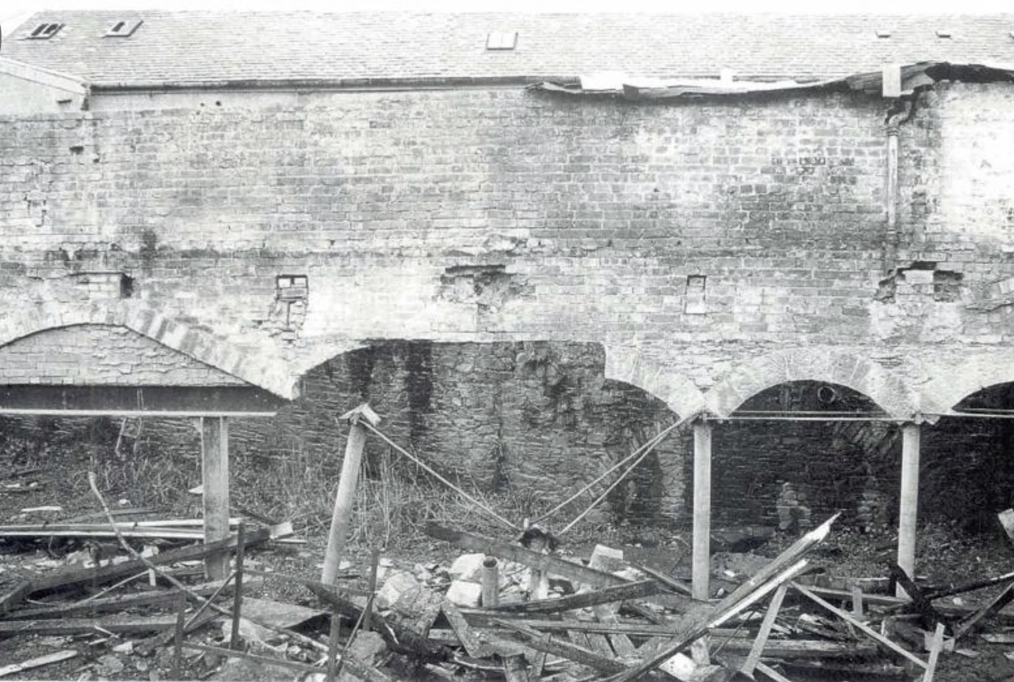
I came across this rather interesting photo, which shows the remains of a partially demolished nineteenth century mill. 


The picture is dominated by a large brick wall, which is suspended above ground level. The original load-path for its support appears to have been an arcade consisting of cast iron columns carried on masonry arches. 

To the left of the image one of the arches has been altered. The profile of its voussoirs has been straightened on one side and the arch infilled with modern brickwork. The infill brickwork is in turn supported on a modern beam and post structure, which is likely formed of hot rolled steelwork.

Below the centre of the wall two of the cast iron columns have been pushed over. The one on the left is clearly visible, while the one on the right is a little harder to pick out. Its head can be detected, because it is still connected to the wrought iron rods that would have been used to resist thrusts at its abutments. To the right of the photo the rods can still be seen linking the remaining iron columns.

It is also evident that the masonry arches which would have been carried by the missing columns have collapsed. It is assumed that rubble, which can be seen at the base of the picture, is what remains of them.

What is of course remarkable is that the brick wall continues to stand. It has found a way of bridging between the steel column on the left and the cast iron column on the right. This is interesting for several reasons.

Since the span is roughly equal to the height of the wall it is reasonable to assume that it has achieved this feat by acting as a deep beam. Were the deep beam made of concrete it would be normal to assess it using a ‘strut and tie’ model. This means imagining a triangular load path in the wall. The two vertices of the triangle form compressive struts, which are sat over the supporting columns, while reinforcement in the base of the wall would complete the triangle by resisting lateral thrusts from the inclined struts. An alternative way of considering this model would be to think of it as a tied arch, as the principle would be similar. Indeed, post failure the residual brickwork appears to have formed a crude arch between the column supports.

In this case there is no concrete and no reinforcement, because the wall is made of brick. Brick is good in compression, which would seem to make either an arch, or compressive struts, a viable load path, however there is no equivalent for the reinforcement, which is required to complete the triangle. 

Brickwork is poor in tension and therefore the base of the wall ought to have failed, however there seems little evidence of distress other than the smaller arches giving way to form a larger, if somewhat makeshift arch.

This means the deep beam must, on this occasion, have a different mechanism for resisting lateral thrust. Two options seem plausible, though one seems more likely than the other. 

It is possible that there are rigid load-resisting structures located just out of picture on either side of the image, however if this were the case then there would be no need for the wrought iron ties, which originally held the column heads together.

It seems more likely that the weight of the brick located above the arch supports is sufficient to divert the arch thrusts back to the vertical i.e. it behaves like heavy bridge abutments. Both headers and stretchers can be seen in the brickwork suggesting that the wall is at least a full brick thick and would therefore be relatively heavy.

Looking carefully at the image there is also evidence of pockets in the brickwork, which would have seated beams in the wall. In fact the remains of an I-shaped steel beam can still be seen embedded on the left hand side. It was presumably easier to cut the beam off at the support than to completely remove it during prior alteration works. This may be relevant because the load carried by the wall must have been reduced. This in turn means the thrust is less.

Since two columns are missing we would ordinarily expect those which remain to take 100% more load. For this reason a reduction in load carried by the wall is of significant benefit to the columns too.

So it would seem that a structure whose intended load-path has been compromised has managed to find an alternative load-path demonstrating rather well that structures will exhaust all possible ways of standing before they collapses.

This does not mean that we would necessarily wish to rely on this load path in the long-term, but nevertheless it is a reminder for engineers that there is more than one way of looking at a problem….in this case an accidental bridge.


Sunday, October 11, 2020

On Waterloo

One of the questions sometimes asked of scientists is whether learning how the universe works somehow diminishes their sense of wonder and mystery? I am not a scientist, but I have been interested in science ever since I was a child. I cannot speak for anyone else, but my answer would unequivocally be no It does not diminish my sense of wonder; it actually increases it.

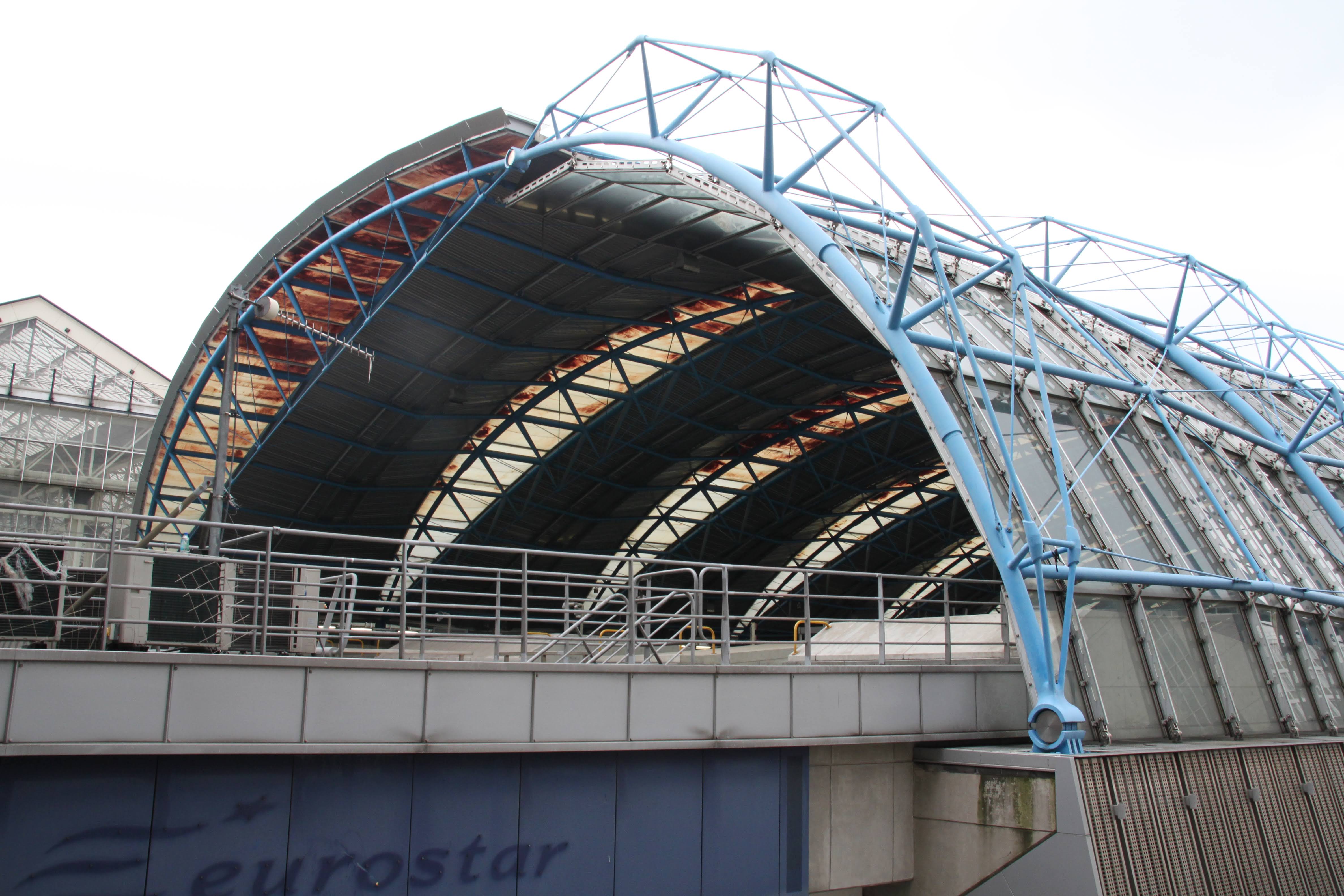
The image below is of the Eurostar terminal at Waterloo station in London. The terminal was closed in 2007 when it was replaced by St Pancras, which is why it looks a little tired. Nevertheless, I think that it remains an elegant structure, however the question arises does it provide more or less wonder when you know how it works? I will leave it to the reader to decide.


The first thing that anyone looking at the structure should understand is that its form is deliberate. In common with many significant structures it is not an architectural whim. The respective roles of the architect and the engineer in relation to aesthetics is not the subject of this post, however I do hope that it will leave the reader with an increased appreciation for the engineer’s contribution.

The next thing that we should note is blindingly obvious.  The structure is formed of a series of steel arches, however the arches are certainly not conventional. They are formed from two curved trusses joined with a pin at the crown and further pins at each of the two bases; though only one of them can be seen in the photo.

Another observation that we might make is that the depth of the truss on the near side projects above the roof while the situation is reversed on the far side. Similarly, while both trusses have three longitudinal chords, the two outer chords are more slender on the near side and the single inner chord is more slender on the far side.

A more subtle observation would be that the thicker chords get thicker towards the middle of their span. This is seen most clearly on the near side. 

Less obvious, due to the angle of the photograph, is that the overall span of the arch is not symmetrical. The span of the near side truss is shorter and more steeply inclined. 

If these forms are deliberate the question must be asked; what on earth is going on? To answer this question we cannot avoid learning some basic structural principles. The first of these is the principle of strut buckling.

If we were to apply load to a short squat object, for example a rock, we would effectively have to apply sufficient force to crush the rock before it would fail. The same cannot be said of, for example, a thin branch taken from the edge of a tree canopy. If we apply a compressive force to the branch it will bow in the middle and fail in bending long before the compressive strength of wood has been reached. This effect is known as strut buckling. There is clearly a relationship between the length of a member and its predilection to buckling in compression. As it happens buckling capacity is proportional to the square of the length.

Conversely the load which causes a member to buckle in compression can by applied to the same member in tension without effect. We all know this in principle, but perhaps without realising it. Consider the absurdity of trying to apply a compressive load to a piece of string and compare that with an application of tensile load to the same piece of string.

We may now apply this logic to the structure in the photograph. Those members with a thick cross section can be inferred to be in compression to avoid buckling while those that are slender must be in tension.

This inference is interesting in so far as it goes, but if we are to follow the logic to its conclusion then that would mean compressive and tensile forces must reverse either side of the central pin. How or perhaps why should that be so? Surely, everyone knows that an arch is a compression structure so what’s going on?

I think the answer lies in the asymmetry of the arch. Supposing there happens to be a day of heavy snowfall. It seems reasonable to suppose that the snow would slide off the steep side of the arch while settling on the flat side. Perhaps there is also a light wind that exacerbates the effect by causing the snow to drift further onto the flatter far side. There is now an uneven load on the arch due to both the self-weight of the asymmetric arch and the snow that has gathered on top.

This would of course cause the far side of the arch to dip while the near side would respond by rising. At some intermediate point the arch would be neither up nor down. We call this the point of contraflexure and amazingly its position will almost certainly correspond with the position of the pin at the crown of the arch; almost like someone intended it to be so.

Once we have grasped this idea the next mental step is not too far away. If the near side has risen the outside chords of the truss will be stretched while the inside chord will be squashed. On the far side the relationship is reversed. We now have an explanation for exactly why the members are fat and slender on each side of the arch. 

We can also make the quite reasonable assumption that the compression chords get thicker towards the middle, because that is the point at which buckling wants to occur. 

The only question left is why the arch is asymmetrical in the first place. It could be because of the route the railway takes into Waterloo station and the implications this has on the shape of the structure……or it could be an architectural whim. It’s a bit of a mystery, perhaps I’ll let you decide.


Sunday, October 4, 2020

On Camping

Some observations about tents


A recent camping trip got me thinking about how tents work; specifically my own. I think it seems obvious to most casual observers that tents are tension structures, but perhaps there is also more to it than that.

I like camping, but I am not obsessive about it. I am therefore not sure if there is a specific name for the type of tent that I own. I shall simply be referring to it as a horseshoe tent, because its cross-section is roughly that shape.

The horseshoe shape is created by an exoskeleton consisting of three arches, two larger ones at the front end and a slightly smaller one at the rear. The smaller one is inclined a little towards the rear of the tent. The rear of the tent is also the location of the sleeping compartment, which is hung between the two arches closest to the back.

The arches themselves are formed of thin plastic tubes, which slot together to form long flexible rods. These are held together by an elastic chord which passes through their center and allows them to be folded away without coming apart. Each rod is inserted into a long pocket stitched to the tent’s waterproof flysheet. Each end of the rod is then inserted over a brass pin attached to the base of the flysheet. Each pin is connected to its neighbour via a nylon strap, which sits beneath the tent’s ground sheet. In the photo below you can see them on the grass before the ground sheet has been laid. 


This is the first structural feature of the tent. The flexible arches have a natural tendency to spring apart, but the tension strap prevents them from doing so. It locks the springiness of the tent rods into place and keeps the rather thin structure rigid.

The next structural feature of the tent is its guylines, which we shall divide into two. The transverse guys i.e. those in the same plane as the arches have only one role, at least so far as I can tell. They anchor the tent to the ground, via the arches, and prevent uplift in stormy weather. I believe this to be the case, because the tent will stand happily without them in calm weather. 

The second set of guylines we shall call longitudinal guys. They are located to the front and rear of the tent. I am sure that they help anchor the tent in stormy weather too, but they also have another, perhaps more important role, as I suspect the transverse guys could do most of the wind resisting work themselves.


It seems to me that the primary role of the longitudinal guys is to stretch out the shape of the tent and to provide it with longitudinal stiffness. The more taught they are made, by adjusting the tensioners, the more rigid the tent becomes. 

It is self evident that to ensure equilibrium i.e. to stop the tent being pulled either forward or back the front and rear guylines must balance each other. What is perhaps less obvious, and is therefore more interesting, is what happens to the tension force after it leaves the guylines. Put another way, what happens between the front and rear guylines to ensure equilibrium. This is what caught my eye and is the underlying reason for this post.

While erecting my tent I had become a little frustrated that the flysheet appeared to be wrinkled and was not sitting flat and smooth as I thought that it should. Then I noticed that the wrinkles had a pattern and that pattern was structurally significant. 

I realised that in any other context an engineer would describe a structure like a tent’s flysheet as a stressed skin. Stressed skin structures resist out of plane loads, for example the wind, by being stretched tight. 

Normally a stressed skin will be fixed along the edges either with a continuous seam or with fixings at close centres. This is because you want the load to be imparted into the thin stressed skin in an even manner. This is not, however, the case with tents.

The tensile loads, which convert the flexible flysheet into a taught stressed skin structure, are imparted at discreet points by the guylines. In the case of my tent via the thin rods that form the horsehoe arches.

The slender rods have little stiffness perpendicular to the arches they form and are of little assistance in distributing the tensile load from the guylines. It is therefore no coincidence that the observed creases extend diagonally from the guyline connections on one arch to the base of the adjacent arch, where it is pegged to the ground.

On closer inspection there is a second set of creases, which start midway between the guyline connection and ground level. This happens to be the point where the rods are connected to the flysheet with plastic clips. 

The question arises, why does the fabric crease and what does it indicate? 

As the flysheet has little thickness it is not good a distributing concentrated load across its own surface. For this reason load applied at discreet points by the guylines causes localised stress in the fabric between points of restraint. Since these parts of the fabric are subject to more stress they stretch more than neighbouring fabric causing the observed creases to appear.

What this phenomena indicates is none-other than the arrangement of internal forces, one might say the load path, in the flysheet. We can visibly see that it has taken up the form of a truss with node points at the parts of the tent that are held stiff. Structures do not often reveal their load path in this way, which makes it all the more interesting.

It is also interesting to note that there are diagonal creases near the top of the tent too. These appear to be the result of the additional section of flysheet that helps ventilates the roof and provides additional stiffness.

One can also detect some creases in a rectangular section of the flysheet at mid height of the first bay. It is difficult to see in the photo, but at this location there is a clear plastic window, covered on the inside by a canvas flap that is used to blank the window for privacy. The clear plastic is a stiffer material than the flysheet around it.

Something else that interested me was why the direction of the creases was in one direction rather than the other. The answer I believe lies in the different geometries, which exist at the front and rear of the tent, and thus vary the angle at which the guylines apply load to the structure. That said, I am also curious to know whether the order in which the guylines were tightened also plays a role. Next time I pitch the tent I shall reverse the sequence and see what happens.

The final observation that ought to be made about my tent, or any tent for that matter concerns the effectiveness of tent pegs. These are short lengths of wire, which are pushed into the ground in order to provide resistance to the the tensile loads in the guylines, including those generated by the full force of the weather. This seems remarkable given their small stature. 

While the angle at which the pegs are pushed into the soil is surely important, friction between the soil and the circumference of the pegs is the primary guard against the pegs being pulled free of the ground. Thus, we can see the ability of friction to resist load is not to be underestimated. It is this same force by which many buildings are supported in soft ground on concrete piles, though in this case the piles are in compression rather than tension like tent pegs.

So it turns out that I needn't have been concerned about the creases in my tent; there doesn’t seem to be anything I could have done about them. This of course wasn’t the main reason I enjoyed my camping trip. Good humour and good company had something to do with that too, however it was quite interesting.


Sunday, September 27, 2020

On Stegosaurus

The original idea for this post was to show an animal’s skeletal structure and explain how it works. I have chosen to do this using a stegosaurus skeleton for two reasons. 

Firstly, this blog is going to be a bit speculative, because I don’t know anything about animals or their skeletons. In the event that a biologist or anatomist finds him or herself reading this blog there is a high probability I shall be politely informed that I don’t know anything. Based on this I figured that my best form of defence would be to choose an animal for which there are no living examples. This way I can argue that since there are no living examples what said animalist thinks they know is mere speculation. No-one can prove otherwise.

Secondly, stegosaurus is a dinosaur and dinosaurs are cool, every kid knows that. Of course I could have chosen T-rex or triceratops, but I think those are the obvious choices and I happen to like stegosaurus so that’s what I’ve chosen.  Here goes….

It seams to me that the spine of an animal, which supports its head and tail are analogous to a thin flexible truss; in fact a special type called a vierendeel truss. To explain this I am going to need to make a few assumptions. Self-evidently all animals walk, run, jump, climb and so forth. Okay, I don’t know whether the last two are true of Stegosaurs, but neither do you. See how effective that defence is? Anyway, movement gets a bit too complex for my stated aim of explaining how skeletal structures work. With that in mind I am going to assume, for the purposes of this blog post, that we have a stationary stegosaurus standing on all four legs.


Based on this the first observation we shall make concerns the legs. The fore-limbs, compared to the hind-limbs, are rarely small, however they are still stocky and have the appearance of being load bearing. The larger hind-limbs and pelvis are larger and would appear designed to carry greater load. This corresponds with the head and neck being rather small when compared to the size and bulk of the hind-quarters and tail.

The stegosaurus’ spine bridges between the two sets of legs and cantilevers beyond them at both ends in order to carry the neck and tail. To understand the structural implications of this arrangement we must first learn something about bending moments.

A bending moment is a turning force whose magnitude is the product of force (or weight) multiplied by the distance (known as the lever arm) to the nearest point of support. The greater the distance to a support; the greater the bending moment.

Consider if you will the following thought experiment. Supposing the stegosaurus’ fore-limbs were located at the end of its nose. I know that’s daft, but run with it. The distance between the nose and its legs is zero therefore no matter how heavy the nose the resulting bending moment is zero.

Now suppose the fore-limbs are located at the back of its head. The bending moment has increased from zero in proportion to the length of its head. I hope you can see where I am going with this. Now suppose the fore-limbs are back where they should be attached to the shoulders. The bending moment has now increased in proportion to the length of a stegosaurus neck and head.

If we were to portray the magnitude of the bending force graphically it would look like a triangle, being zero at the nose and increasing to a maximal point where the legs meet the shoulders. We could repeat the same process starting from the tail. The bending shape would be the same, though the height of the triangle would be bigger because the tail is longer and heavier.

We are now left with the bit in the middle, we need to join the two triangles together. Of course the  body of the stegosaur is somehow attached to the spine (I told you I am not an animalist). We’ll get back to that subject later, but for now we will simply note that the weight of the body must pull down on the spine. It follows that a line depicting the bending moment will join the two triangles, by sagging in middle. It might look a bit like the diagram below. 


The interesting bit; also the bit where I might start to get into trouble; is how the spine resists these bending forces.

The first thing we notice about a stegosaur spine is, like most spines, the odd shape of the vertebrae, which is distinguished by three parts, at least to my eye. There is the oval shaped portion located at the anterior. The lower part is of bone and the upper part has a hole where the spinal cord would be. 

The second feature is the piece of bone that projects vertically from the middle of the vertebra to form the posterior.  This is where the ligaments and muscles of the back are connected to the vertebrae.

The third feature is the two transverse projections; one either side of the vertebrae. These are where muscles and ligaments attach to the spine and are also the points from which the ribs are articulated. The fossil stegosaurus vertebrae pictured below is quite tall and for reasons that will become clear is postulated to be from the lower part of the back.

When the vertebrae are aligned in a row, as they would be to form a spine, they start to resemble a truss with a lower chord of bone and an upper chord of ligament and muscle. You have to imagine the muscle and ligament joining the vertical projections together, as self-evidently they haven’t been fossilised. The internal members of the truss are formed by the bone surrounding the spinal cord and the projection that extends from it. There are of course no diagonal members and that is why the resemblance is to a vierendeel truss.


For this information to be of use we now need to describe how a truss works. We shall begin by considering a beam, which is altogether a simpler and humbler form than the truss. 

If a beam spans between two supports, one at either side, it will deflect in the direction of the bending force to form a curve. As the beam deflects the outer edge of the curve is stretched and is evidently in tension. Conversely the inside edge is squashed and must be in tension. The centre of the beam, known as the neutral axis is neither in compression nor tension; it is at rest.

If we apply the same logic to a truss the outer chord of the truss carries a tensile force and the inner chord carries compression. The internal members of the truss transfer load between the outer and inner chords. 

In the case of our stegosaur based truss the ligaments and muscle at the posterior are ideal for carrying tension and the boney part at the anterior is ideal for resisting compression. This is remarkably good luck, because as nature would have it, the bending moments imparted by the tail and neck of the stegosaur, as shown in our earlier diagram, impart tension on the posterior side and compression on the anterior.

If that is not remarkable enough the depth of the vertebrae increase towards the hind limbs to match the increasing magnitude of the bending forces. Nature has actually fine tuned the size and shape of the vertebrae so that the resulting truss matches the shape of the bending forces to which they are subject.

Having made this observation it is tempting to end this post satisfied that our work is complete, but I am not quite ready to do that. There is one more thing that is just too interesting not to pass comment. I also noted earlier in the post that I would return to this subject.

It is not lost on me that the stegosaur spine has a very distinct curve, which given the apparent fine tuning of the vertebrae, cannot be without reason. Based on that it is, I think, worth a further speculation. 

It strikes me when looking at the bulk of a stegosaur’s body, how is that great big, heavy fleshy part of the animal supported from the spine. Presumably it somehow hangs? I imagine the animal’s flank muscles, perhaps reinforced by the ribcage, are responsible for transferring the load.

It then strikes me that an arch is a rather efficient way of supporting the load and transferring it to the legs. There is of course a potential issue with this load path. Arches generally have large abutments whose purpose is to resist the lateral thrusts generated at the base of an arch and thus prevent it from spreading. It is these same thrusts that make it so difficult to build a house of cards. Of course stegosaurus have no abutments.

There is a potential solution, which is to be found in the form of a bow string arch. Sometimes when there is no opportunity to provide bridge abutments the engineer will instead join the arch supports together with a tie member. This works by causing the two sides of the arch to pull against each other. Since the pull is equal and opposite equilibrium is maintained and the arch is prevented from spreading.

My final speculation is therefore that the stegosaurus’ sternum and chest muscles provide a tie, which form’s a bow string truss made of meat and bone.

Now I can finish the post and wait to be shot down by people that know what they’re talking about. I shall be lying in wait with my pre-prepared speculation defence.

Sunday, September 6, 2020

On Snow & Ice

Engineers are supposed to be numbers people who thrive on logic, objectivity and data. Engineers are not supposed to appreciate subjectivity; and we’re definitely not supposed to like art. At least that’s the theory. The truth is that art isn’t always as subjective as you might think and engineers can and do like art.

Fillippo Brunelleschi is most famous for designing the dome of Florence Cathedral. It is a spectacular structure designed and built using an exceedingly novel method of construction. Both architects and engineers claim Brunelleschi as one of their own, yet his apprenticeship was served in the Arte Delle Seta, where he became a master goldsmith and sculptor. That is how it was in the Renaissance, master builders and designers learned about material and form in the artist’s studio.

One of my favourite modern artists is Andy Goldsworthy. I wouldn’t remotely consider myself an art critic nor would I claim to know what Mr Goldsworthy was thinking when he conceived a particular piece, but I am going to speculate that he has developed a keen sense of material and form through hours of trial and error in the artist’s studio.

I have made this speculation, because he succeeds in combining natural materials with shapes and forms that make complete sense from a structural perspective. He appears to understand exactly what he is doing.

Perhaps my favourite examples of Goldsworthy’s work are those which he creates from snow and ice. I like them for several reasons. The first is because snow and ice illustrate particularly well that material properties can and do vary. For example ice remains solid when cold, but melts when warm.

Just as important, but perhaps more subtle, snow can be squashed and moulded into different shapes while ice is hard and brittle. It would rather fracture than bend.

Both materials have a dislike for tension; though they express their dislike in different ways. Snow will disintegrate and crumble, while ice will crack and fracture. Conversely both snow and ice will quite happily resist compression without difficulty.

It turns out that materials, like people, have temperaments that must be understood to get the most out of them. This Goldsworthy achieves exceedingly well.

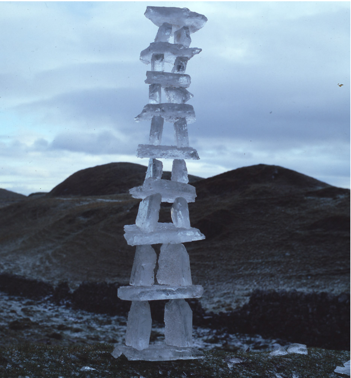
If we consider, for example, the ice sculpture shown below. It consists of eight storeys each resembling the columns and entablature of a greek temple or if you prefer the sarsens at stone henge.


Just like the designers of those ancient structures, Goldsworthy has realised that tension is the enemy he must subdue. By placing the ice columns close together he prevents the lintels from developing excess tension on their soffits. For a similar reason the columns have been carefully aligned so that load can travel from top to bottom in direct bearing.

Further examples of matching form to material are shown in the sculptures below. One shows an arch constructed from thin wedges of ice and the other from stone and snow. Both resemble the classical form of a traditional masonry arch. 


It is of course well known that arches are compression structures and are therefore inherently suited to materials that dislike tension. With an ample supply of stone, and a primitive form of concrete, it is unsurprising that Roman architecture features arches so prominently.

That said, it is Goldsworthy’s decision to construct his arches in the traditional way using wedges that is interesting, particularly the one made of ice. This choice allows us to get a deeper sense of how arches work.

After finding ourselves unintentionally seated on the ground, everyone has undoubtably discovered that ice is slippery. Knowing this to be true why don’t the pictured ice wedges at the crown of the arch simply slip past each other, under the action of their own self-weight, thus causing the arch to collapse? This is not a trivial question.

In 1695 the Frenchman Philippe de la Hire was the first to compose a theory of masonry arches using mathematics. He began by assuming that the wedge shaped stones (voussoirs) from which arches were formed have infinitely slippery surfaces i.e. the joints between them are frictionless. He then set about tackling the question, how heavy [and by inference how thick] should the voussoirs be to keep an arch stable?

In this most slippery of scenarios it is, by definition, impossible for forces to develop parallel to the joints between voussoirs. The weight of the arch must therefore thrust exactly perpendicular to the joints.

It can be seen from the photos above that the wedges of ice [and thus the joints between them] are vertically aligned at the crown of the arch and therefore at this point the weight of the arch must act horizontally i.e. perpendicular to the joints.

Moving away from the centre of the arch the inclination of the ice becomes steadily flatter. Since, the weight of the arch must still act perpendicular to the joints it is bent around the curve of the arch. 

This is where the problem starts to get interesting. If the arch is built on a flat base, as shown in the image above, La Hire discovered that the weight acting at its base must be infinite or the arch will be unstable, which is obviously wrong.

La Hire rightly concluded that friction must therefore be present between the voussoirs [even if they are made of ice] though it was left for others to account for it in subsequent theories. It is this frictional force that stops the wedges of ice slipping from the arch’s crown.

In some ways it would be satisfactory to end here, but we are not quite ready to finish. There is something else that turns out to be important, which we have not yet discussed. Thus far we have been taking about wedges or voussoirs and the analogy holds reasonably well in the instance of the Goldsworthy’s snow arch.

In the case of his ice arch the analogy is a little imperfect, because the shards of ice are in fact flat and not really wedge shaped al all. We would normally think of a wedge as having a fat and a thin end.

This doesn’t at all undermine what we have said thus far; all of that still holds. What is interesting is that without a fat and thin end the shards of ice are in contact on the inside of the arch, but gaps necessarily open up at the outside edge. The thicker the arch the more pronounced would be the gaps.

The significance of this is the contact area between the shards of ice is only a fraction of their surface areas. Since the ice does not fracture we may infer that the stress in the arch must be quite low and would certainly be in no danger of crushing its component parts. 

This principle was demonstrated in 1846 by Barlow at the Institution of Civil Engineers in London. He built a model arch with six voussoirs using slender prices of wood en lieu of mortar. In progressively withdrew the slips of wood in three locations to show the stability of arch would be maintained.

Taken together the thoughts we have outlined illustrate the key principles of masonry arch design. Namely, friction must be present between the stones; the strength of the stone is of little importance; and finally the stability of an arch relies entirely on its geometry and weight. Since weight is a function of geometry and friction is a function of weight we might just as easily say the stability of an arch is a function of its geometry.

I have no idea whether or not Andy Goldsworthy’s thinking has extended this far, nevertheless the question was worth addressing, because the answer surely enhances our appreciation of his art.

Now I realise in reaching this point that some may be thinking that I have, in discussing geometry and forces, undermined the original premise of this post. You might say that I have turned art into science.

I beg to differ. 

Isn’t the point of modern art it’s subjectivity? Isn’t it supposed to make us think individually about what it represents and then decide how that makes each of us feel? Well, in my subjective view this is what I think it represents. It satisfies my curiosity and that makes me feel happy.


On Ice Shelf Cracking

Tension Cracks in the Brunt Ice Shelf Yesterday the BBC news website published images showing a large section of the Brunt ice shelf in Ant...