Showing posts with label buildings. Show all posts

Sunday, August 8, 2021

On Pendentives

A tale of two domes

Perhaps two of the most important domes from antiquity are those belonging to the Pantheon in Rome and the Hagia Sofia of Istanbul. Although the latter is to be found in modern day Turkey, it is of course from the era of Byzantine rule in Constantinople and is therefore of Roman origin.


From their outward appearance the two domes would appear to be similar, indeed how different can the construction of a dome be? Further inquiry would reveal that the materials used to construct the two domes are different. The Pantheon is made of unreinforced concrete, while the Hagia Sofia’s dome is of masonry. Indeed the Pantheon remains the world’s largest unreinforced concrete dome to this day.


This difference is interesting, but in my view is not fundamental to the way in which these two revolutionary structures work. I am perfectly aware of the Pantheon’s oculus, its coffered soffit, the variation in concrete mix over its height, all of which were designed to save weight. These are important details, which are both interesting and worthy of study, maybe I will write about them in some future point, however they are not directly relevant to the subject of this post.

The first thing to note is that classical domes, like later gothic structures, are what I would describe as gravitational or compressive equilibrium structures. That is to say that their structural adequacy is dependent on their shape and not on materials science. This is possible because actual stresses are compressive and sufficiently low that, providing equilibrium is maintained, material strength is unimportant. This makes sense because materials science, at least in the modern sense of stresses and strains, did not exist when they were built. 

Those familiar with the structures in question will no doubt be aware of known cracking in both domes, which might be taken to suggest that there is in fact some material science going on, however as we shall see this is not the case.

To understand the primary difference between the Pantheon and Hagia Sofia, perhaps it is first necessary to explain how a generic dome works. In section domes behave in a similar manner to arches, because their curved profile exerts both vertical and lateral thrust at the seating[1]. Domes are of course unlike arches in the sense that they are 3D structures. This means that the aforementioned vertical thrusts are expressed as compressive meridional stresses extending from the crown of the dome to it’s base. The lateral thrusts push outwards in all directions generating a circumferential or hoop stress that cause domes to spread. It is the way in which the meridional and circumferential stresses are resisted that makes the difference.

Like barrel vaulted structures from the classical period of history the Pantheon is supported on heavy walls that follow the profile of the roof structure, in this case a cylinder, in order to buttress the roof against spreading. Some descriptions I have read speculate a stepped thickening observed at the dome’s base is designed to provide a circumferential tie. Maybe their authors have done more research than me and have data to support this view, however I am disinclined to adopt it based solely on my own intuition that the tensile capacity of concrete, albeit Roman concrete, is too low. Also, if tension were present it would imply materials science is at work to provide the required equilibrium, which is philosophically less satisfying.

It occurs to me that a more elegant solution, which maintains the idea of gravitational equilibrium, would be one where the purpose of the steps was to increase weight at the head of the supporting wall in order to push the dome’s thrust line back into the supporting walls. In essence it would behave, at least in my estimation, like the pinnacle atop a flying buttress.


The dome of the Hagia Sofia is different. It does not find support from heavy buttress walls. Rather it straddles the four corners of a vast open space into which light and air may flood. In character it is a medieval structure whose load paths concentrate the dome’s weight into a carefully defined masonry skeleton. The invention that makes this possible are the inverted triangular masonry panels, known as pendentives, that are located over the four supporting piers. As they spread outwards from their apex a series of four arches are formed on the dome’s perimeter. Together these elements funnel load into the supporting piers where the in plane arch thrusts are buttressed.

It is evident however that there remains unbalanced thrusts perpendicular to the apex of each pendentive arch. Equilibrium is restored by hemispherical domes that lean in the opposite direction to the dome’s thrust in one direction and buttresses in the other.
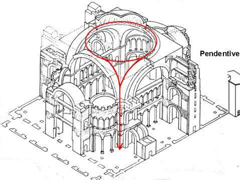

And so it is that the dome at Hagia Sofia represents a transition between heavy buttress walls and gothic cathedrals of the later medieval period, whose structures had a more clearly defined order of primary and secondary elements and a more sophisticated understanding of load paths.

Now, to the aforementioned cracks in both domes. Many seasoned observers hold the view that these are the result of past seismic events and differential settlements. Indeed the original dome at Hagia Sofia is known to have collapsed during an earthquake leading to the present cupola being constructed with a higher profile in order to reduce the magnitude of lateral thrusts. 

Nevertheless it would appear that in spite of movement to both structures gravitational equilibrium has been restored. They remain stable, or at the very least, are moving very slowly.


[1] For further information I have written several prior posts relating to the behaviour arch structures.

Sunday, July 11, 2021

On San Petronio

Gravitational equilibrium & the square cube law


‘Gulliver’s Travels’ is a classic of English Literature written by Jonathan Swift in 1726. It is intended to be a satire of human nature and ‘travellers’ tales’. In the book its protagonist visits the fictional countries of Lilliput and Brobdingnag. The citizens of the former are 12 times smaller than Gulliver and in the latter they are 12 times bigger.

Of course every reader of the book knows that Lilliput and Bribdingnag are fictional, but perhaps fewer might realise that they are necessarily fiction in any possible world that follows the same physical laws as our own. The reason for this is described by the square cube law, which was first attributed to Galileo.

According to this law the size of things cannot be indefinitely scaled up, because the physical properties of objects change as they increase in size. Consider a cube with sides one unit long. If we were to double the length of each side then the surface area of each face will increase from 1 to 4 units. The volume of the cube, and by extension the quantity of stuff from which it is made, increases from 1 to 8 units i.e. doubling the linear dimensions causes the surface area to be squared and the volume of stuff to be cubed.

In other words the rate at which the volume and weight of an object increase with size is greater than the rate at which its linear dimensions and surface area increase.


Conversely, the strength of things, normally expressed as a limiting stress, is independent of size
[1]. It follows that as things become larger, while retaining their original proportions, they will eventually reach a point where they can no longer support their own weight. This places an upper limit on how big things, including people, can get.

This is a vexing problem for modern day architectural students, who are surprised to learn that the model they have spent hours building does not prove that the structural gymnastics their design requires are viable in the real world.

There is of course an exception to the square cube law, though not a true exception. The square cube law does not cease to work, rather it is not discernible within the normal range of scaling for certain objects.

An example of such an object from the natural world would be a mountain. An equivalent structure form the man-made world would be a pyramid. Both structures come from a class of things that share three key ingredients. Firstly, they are both made of stone, which is a natural material with a very high compressive strength and low tensile strength. Secondly, they are both compression structures that assiduously avoid tension. Thirdly, they are stocky and solid structures. Not solid in the sense that they are strong, though that is indeed true, but solid in the sense that they are not hollow. The implication of being stocky and solid is that they are not prone to buckle, as a slender or thin walled structure is. A second implication of stockiness is a large cross-section, which implies low stress.

These then are the ingredients for subverting Galileo’s square cube law and within the class of things which have these ingredients there is a group of structures that does so with a style and panache that is difficult to surpass. They laugh in the face of the square cube law.

I am of course talking about gothic structures; those great stone cathedrals of the late medieval period with their quadripartite vaults and flying buttresses. I am often asked, mainly by my dad, how it was that medieval masons created such structures in the absence of modern structural theory. The stock answer is that they used rules of thumb, but for me there has to be more to it than that.

How on earth did they manage to design structures, using rules of thumb, that modern analysis shows us to have near perfect proportions. Rules of thumb are intended to apply generally, but must necessarily be derived from the particular. The further a design departs from the particular the less useful a rule of thumb is. 

Gothic structures do have similarities, but there is also great variety in their design, which ought to make rules of thumb less helpful.

Perhaps the answer to this dilemma is to be found in a process of trial and error. While there was undoubtedly a role for trial and error I am not convinced that it played a central role, at least not in the commonly understood sense. I hold this view for several reasons:

Firstly, most cathedrals took hundreds of years to build and though master masons may have worked on several, they would not, in their own lifespan, have time to learn all the necessary forms by trial and error. This brings us back to rules of thumb. Secondly, while there is evidence of design evolution over time there is relatively little evidence of major failures, which is odd given the innovative, and often spectacular, designs adopted. Furthermore, when known failures occurred they were often, though not always, associated with abnormal events like earthquakes or phenomena external to the structure like differential settlement.

We therefore have much evidence of trying daring new things, but scant recorded evidence of failure [2]. This is not entirely a surprise, because cathedrals are expensive and their proprietors were not stupid. Master masons would not have been in charge for long if their structures kept collapsing.

To find a satisfactory explanation I think we need to return to the square cube law. If a structure could be designed to subvert the square cube law then a successful pattern would be successful at any scale. It follows that if you could demonstrate a particular form of structure would stand using a small model made of wood then it would also stand if it was scaled up to full size. 

I do not know whether masons understood that they were subverting the square cube law. I suspect that they didn’t, but I do think that they understood perfectly well the load-paths and principles that were necessary to keep a stone structure in equilibrium. I think they fully understood that tension was the enemy and that gravity must be harnessed to maintain compression in all parts of the structure. 

They were specifically designing structures to achieve gravitational equilibrium and they were doing it by experimentation with scale models. They then used rules of thumb, derived from these models, to scale up their findings to full size structures.


Happily for the masons this methodology was just perfect for avoiding the square cube law, whether they knew it or not, and in this way spectacular and innovative designs could be realised without needing to know anything about materials science, stresses or strains.

While this theory involves a heavy dose of speculation it is not without evidential support. For example, we know that Antonio Vicenzo the designer of San Petronio church in Bologna commissioned a model of brick and plaster at circa one eighth scale. It was around 19m long and 6m high. I expect that it was used to convey the design to its proprietors, but I don’t think it is too great a leap to posit that it might also have played a role in the church’s structural design.


[1] I accept that all bets are off at the atomic scale, but we don’t normally consider atomic forces when designing building structures, bridges and the like.

[2] I know that absence of evidence is not evidence of absence, nevertheless evidence is sometimes notable by its absence, particularly when there might be a reasonable expectation to find some.


Sunday, June 27, 2021

On Lunes & Cracks

Conserving St Peter’s Basilica


The dome of St Peter’s Basilica in Rome is one of the most recognised structures in the world. It was completed around 1590 and was conceived by the genius Michelangelo. There are many reasons why it is special structure, but perhaps the most important is amongst the least well known.

By around 1680 cracks were being reported in the dome, which unsurprisingly caused some to question its safety. Concerns were exacerbated following an earthquake in 1730. Meridional cracking, associated with a dome’s tendency to spread at the base, was well known in the sixteenth century and therefore, following a detailed investigation, a recommendation was made to supplement the existing wrought iron hoops, which were intended to prevent spreading, with three or four more.


It would seem that the Vatican had travelled a distance since Galileo’s heresy trial and the incumbent Pope Benedict XIV, unlike many designers and practitioners of the day, was impressed by the progress made by scientists and mathematicians of the day. He therefore commissioned three of them; Thomas Seur, Francois Jacquier & Roggiero Boscovich to examine the subject. The publication of their findings in 1743 was a seminal moment for Structural Engineering, because they had based their conclusions on a mathematical analysis of the dome. It was the first known occasion when this was done in any meaningful way. Their approach included a model of the dome’s weight, its materials and two different behavioural scenario’s. The method they adopted for combining this information would today be called ‘virtual work’.

They concluded that the existing iron rings embedded within the dome were insufficient to prevent spreading and that the dome would collapse. They therefore proceeded to calculate the number and proportions of additional rings. This was of course a safe recommendation, however it overlooked the rather important fact that the dome had not in fact collapsed and was very much still standing.

Though they were three of the smartest mathematicians of their day they had made the same basic error that almost every graduate engineer makes at some point. They had placed their confidence in their model over what they could see with their eyes. One of the most important truisms of structural engineering is that a structure will remain in place until it has exhausted every possible means of standing. Consequently, if a mathematical model says a structure will collapse, but it stubbornly refuses to do so, then one is obliged to conclude that the model is wrong and not reality.

The presiding committee responsible for the church’s upkeep did what committees often do. They ignored the expert report and continued to monitor the structure. Benedict was also dissatisfied, but wished to persevere with a scientific approach. He commissioned a new study by a different expert Giovanni Poleni. 

Poleni criticised aspects of the first report and tackled the problem with a different approach. While he conceived his own mathematical model, Poleni was also aware of Robert Hooke’s work on the stability of arches, which is described in an earlier post [On Balloons, Chains and Arches]. He therefore imagined the dome to be split into a series of lunes each of which rested against an opposing lune on the other side of the dome. He then used a physical model to demonstrate that the line of thrust for a pair of lunes lay within the depth of their cross section and would therefore meet Hooke’s criteria for a stable arch. By this reasoning the whole dome, being a series of balanced lunes, would be stable in spite of its meridional cracks.

Nevertheless, Poleni also recommended four additional wrought iron hoops, which were installed in 1744. A further hoop was added in 1747, when it was discovered that one of the originals had in fact fractured.

While the application of mathematics to structural engineering problems, which was pioneered by Seur, Jacquier and Roggiero, would prove successful in the long run it is not difficult to see why it was unsuccessful to begin with. 

While mathematicians and scientists had been publishing treatise on engineering subjects from the early eighteenth century, architects and engineers of the day were unacquainted with mathematical argument and treatise were therefore largely ignored.

A second, and perhaps more significant issue, was the relative maturity of the respective disciplines. Eighteenth century mathematical models, though brilliant in their conception, were no match for 1,000 years of engineering experience, which had refined and optimised known structural forms about as much as it was possible. The only conceivable  advantage for science would be for the conception of structures for which there was no precedent.

This dichotomy caused a divergence in engineering practise between Britain and its European neighbours. While France and Germany forged ahead with academic schools of engineering Britain largely adopted an empirical approach. Unsurprisingly the continental Europeans produced more impressive academic works, however Britain prospered with its empirical approach, which produced closer alignment with the real world and therefore greater efficiency.

Britain’s engineers did not dismiss theoretical works, because they were less intelligent or less capable. They simply knew that the best academic theories of the day could not get close to matching the empirical approach they were pioneering.

There is a lesson in this for the modern engineer. Modern codes of practise are becoming increasingly academic and less practical. It is not clear to this engineer that the additional effort required to use them yields a justifiable benefit. I am also quite certain that as in the eighteenth century some modern methods are less efficient than the empirical methods they have replaced.

In some circles our profession needs to rediscover the once obvious truth that a theory, which does not match past empirical experience, is not a good theory.....particularly when it is more complex to use than its predecessor.


Sunday, May 30, 2021

On Horseshoe Arches

Why use a horseshoe arch?

Historically many types of arch have been used to construct buildings and bridges. The underlying reasons for adopting each of the main types is normally relatively clear, however in the case of the horseshoe arch this is not so. The Romans predominately used the semi-circular arch. It has a geometrically simple form, which is straightforward to understand and straightforward to construct. It is perhaps the reference point for comparison with other forms.

The segmental arch is much flatter and is often used for constructing bridges. It is less efficient structurally than a semi-circular arch, in the sense that the lateral thrusts are greater. This means that larger abutments are required. The reason for choosing a segmental arch is to avoid creating steep inclines for the ramps onto a bridge. This is the reason heavy abutments are a price worth paying.

Pointed arches are characteristic of gothic architecture. There are very good reasons for adopting them. The first reason is geometrical. The rise of semi-circular arches varies with the span. Pointed arches can have the same rise for different spans. This is a useful trait when vaulting a gothic cathedral. A second benefit to pointed arches is that the lateral thrust at the abutments is less than for a semi-circular arch of the same span. This is also important for framing gothic cathedrals which are propped by delicate flying buttresses. Another reason, which is often sighted, though of little importance from a structural perspective, is that pointed arches can be used to create a higher ceiling. This enabled more light in the building and was viewed as being symbolic in a cathedral structure, because it was closer to God.


Now, returning to the archetype with which we began, the horseshoe or moorish arch. A google search will reveal that the purpose of this form is not at all clear. Even academic writings seem to be rather woolly on the topic. Explanations, particularly in architectural papers, seem to focus on somewhat subjective views about symbolic meaning and many of the structural explanations are far from compelling. 

Some point to the provision of a wider seating, which will reduce the bearing stress at the base. This is of course true, however since the compressive stresses in masonry structures are low to begin with its not really a material observation. 

Others say that horseshoe arches can be built without centring, as apposed to a semi-circular arch, which cannot. This argument makes no sense at all, at least to me. I do not see any property of a horseshoe arch relative to a semi-circular arch that would make that so.

There is a view, which seems to make sense if the horseshoe is seen as an intermediary between semi-circular and pointed arches, that the horseshoe provides a way of increasing the height of a space. It is self-evidently a taller structure than a semi-circular arch of the same span and, prior to the pointed arch, it would certainly be a good way to achieve a more spacious building interior with greater opportunity for light to penetrate.

One might also argue that the horseshoe is simply an aesthetic choice that was favoured by Moorish designers. This explanation is not terribly satisfactory; it would be disappointing if the traditional Roman semi-circle was replaced with a horseshoe just because it looked nice. I think there is more to it than that.

Analysis of a horseshoe arch with the same span as a semi-circular or segmental arch will show that it has a lower horizontal thrust at the base than either of the other two options. This is clearly an advantage, because the abutments can therefore be smaller. That said in order to re-directed thrust from horizontal to vertical the upper part of the arch must resist bending forces, which could cause buckling if the arch is too thin. 

An example of this form of failure occurred in 2004 when the concrete structure of the newly completed terminal 2E at Charles de Gaul airport collapsed killing 4 people.

The tendency to buckle can be resisted if the arch is confined on either side. Indeed, in every example I have seen of masonry horseshoes they are either confined by spandrels or are balanced by other arches pushing with an equal force in the opposite direction. Of course potential buckling forces were reduced by the subsequent development of the pointed arch. 

Nevertheless, if the upper part a horseshoe arch has sufficient bending capacity, in the case of modern materials, or is sufficiently confined, in the case of masonry, then the resulting thrusts at the base of the arch are somewhat reduced and this is a distinct advantage.

One of the reasons I think that Moorish designers knew what they were doing and were thinking about structural load paths is evident in the detail of their construction. It is noticeable that the portion of the arch below the semi-circle is invariably formed of a single piece of stone or from a series of specially shaped blocks that do not follow the standard format of the voussoirs above. This is essentially to ensure that the angle of the joints all point inwards thus making it easier to construct, because the stones cannot slip outwards before the arch has been completed. It likely also makes the arch less prone to fail due to lateral thrust in the permanent case.


In summary I rather suspect that the horseshoe arch was originally developed as a means of amending a semi-circular arch in order to create a taller space. It seems like a logical step to simply use a larger proportion of the circle. Through experimentation, probably with single arches to begin with, the behaviour of such structures started to be understood, which ultimately led to some of the rather impressive arcades and other structures that came to characterise Islamic Architecture to this day.

This is of course a speculation on my part, as I have not completed a detailed historical study of horseshoe arches. I trust however that being based on the structural properties of horseshoe arches, it has at least some interest and merit. I am certainly no less impressed by the clever use of horseshoe arches than I am the semi-circular Roman arches that preceded them or the pointed gothic arches that followed. I also have no doubt that the Moorish legacy of horseshoe arches in Spain would have been an important influence on medieval architecture in Europe thereafter.


Sunday, May 16, 2021

On Gothic Cathedrals [yet again]

Flying Buttresses 


The flying buttress is synonymous with gothic cathedrals. It moves their structural skeleton out with the building envelope and exposes it to view. It is probably for this reason that it is readily identifiable as one of the defining features of gothic design.

The name flying buttress is also interesting, because if they were invented today we might simply have called them props. The term flying buttress is, I think, a reflection of the history and development of masonry structures.

As we have learned in prior blog posts, early barrel vaulted roofs required thick heavy walls to resist the lateral thrusts, which result from the vaults’ tendency to spread under the influence of their own weight. It was possible to obviate the need for heavy wall construction by concentrating these thrusts using ribbed vaults. This meant that the outer walls need only be reinforced with localised buttresses.

This was all well and good if the church had only a nave, however if there were aisles either side, or additional cloisters, then in order to avoid being in the way the buttresses had to be moved farther away from the nave. This led directly to a requirement for masonry props to ‘fly’ from the nave, over the aisles, and onto external buttresses. 

The flying buttress must resist three different types of loading. In the first instance it must resist its own self weight. It does this by forming a relatively flat arch, just like a segmental arched bridge. The vertical weight of the arch is supported on one side by the nave and on the other by the buttress. The lateral arch thrust is resisted by pushing back against the nave vaulting and against the external buttress. The thrust produced by the nave vaulting is much larger than that produced by the self-weight of the arch and therefore both the nave and the external buttresses can readily accept this load.


Of course, the thrust produced by the nave vaults is the second form of loading to be resisted. Unlike the curved load-path from the self-weight of the flying buttresses this load-path is essentially applied in a straight line, which is probably why the top surface of many flying buttresses is linear and not curved like their soffit.

There are two ways in which the nave thrusts may cause the external buttresses to fail. Firstly, they might rotate about their base due to the thrust being applied at their head. This would be an overturning or toppling failure. Providing there is sufficient mass in the buttress to provide a restoring force overturning will not occur. This is primarily a question of geometry.

The second potential mode of failure is a line of shear extending from the flying buttress to the outside face of the external buttress. In this scenario the top of the buttress is simply pushed laterally relative to the masonry below. To prevent this from happening most buttresses have a large pinnacle, whose weight squashes the shear surfaces together in order to prevent a crack plane from forming. It is in effect the application of a pre-stress, much like that which was encountered in a prior post about gothic window tracery.

The final type of loading to be resisted is wind load. Most cathedrals have a large wooden roof located above the masonry vaults. Without flying buttresses to transfer load from the base of the roof into the external buttresses the wind would generate an unacceptable thrust at the head of the nave walls. There is also a view that the weight of large timber roofs would be too great for timber ties to prevent them from spreading and consequently the flying buttresses must provide a load-path for restraint to roof spreading as well as a route for transferring wind load.

It is the requirement to provide restraint to the timber roof, which is responsible for the presence of high level flying buttresses located above those which prop the nave vaults. 

Something else which is interesting about flying buttresses is how load is actually transferred into them. This is not a trivial question. It is perhaps a statement of the obvious to say that flying buttresses are located outside the nave, while the vaults are located inside. What is perhaps less obvious is how load transfers from one into the other.

The flying buttresses are actually located just above the level at which the vaults are sprung on the inside. This is done to help facilitate lateral load transfer.

The masonry walls and piers in a cathedral are not normally solid, as you might suppose, and neither are the vault conoids. They are generally formed of dressed stone either side of a rubble-mortar infill. Medieval masons did not trust the rubble infill to transfer the vault thrusts from the solid ribs and therefore they would include full depth ‘through-stones’ known as ‘tas de charge’ just above the level at which the vault ribs spring from the internal piers. This is reflected in the external level of the flying buttresses.

The tas de charge was generally located at the top of the pier capitals and below the point at which the transverse and diagonal ribs [assuming a quadripartite vault] run together. This section of masonry was formed from several courses of single stones. There are three advantages of using single stone courses.

The first advantage is that they are able to bind the piers together and stop the dressed facing stones separating from the mortar-rubble infill. Secondly, they enable the tas de charge to transfer load into the flying buttresses efficiently. Finally, these courses can be placed without formwork before the ribs are constructed.

From the necessity for pinnacles, to pre-compress the external buttresses, to the positioning of a tas de charge to ensure that vault thrusts are transferred effectively, it is clear that medieval masons understood exactly what the load paths were in a system of flying buttresses and that they had thought about the details carefully. It is also clear that though the concept of a flying buttress is relatively simple there is actually some relatively complex thinking required to execute that concept.


Sunday, May 9, 2021

On Gothic Cathedrals [again]

Quadripartite Vaulting


Another feature of Gothic Cathedrals, which makes their appearance distinctive, is the quadripartite vault. To full appreciate the impact of this innovation it is necessary understand what came before.

The first vaults are often attributed to the Romans, however both the Greeks and the Egyptians are known to have used them. Most early vaults were of the barrel variety, which is essentially a semi-circular arch extruded into the third dimension. The Chaldean version was formed of a series of arches inclined to one side. The inclined angle allowed them to be built without centring, assuming of course that the end was buttressed.


Masonry barrel vaults are useful for bridging long rectangular spaces, however they require heavy walls to support them due to the lateral thrusts imparted at their base. This is the same action that is found at the base of all arches and has been discussed in prior posts.

Since heavy walls were required to support barrel vault roofs it was difficult to fit large windows into the elevations. For this reason early churches constructed in this way were dimly lit. The Romans found an answer to this problem by interlocking barrel vaults in perpendicular directions. This concentrated loads at the junctions between vaults allowing them to be supported on large piers. The junctions between the vaults are known as groins leading to the eponymous name groin vaults. The obvious advantage being the ability to create windows in the elevations.


Groin vaults were structurally efficient, however they required very skilful masons to carve the groins’ complex geometry. For this reason they fell out of favour with the collapse of the Roman Empire.

Subsequently medieval masons introduced their own solution, which is known as the ribbed vault. Instead of constructing groins they bridged the building with a series of masonry ribs. Each bay had two diagonal ribs and three transverse ribs. This is known as the sexpartite ribbed vault, because the ribs divide the vault into six parts.


An advantage of this form is that load is concentrated at six piers, which means that, as with groin vaults, heavy walls were no longer required. Consequently, the space between the ribs can be used to form windows.

Since the ribs convey load to the supporting piers the infill between them need only span the short distance between the ribs. This was an improvement over the groin vault, which meant the infill could be both thinner and lighter. This in turn reduced the weight to be carried on the piers and also the magnitude of lateral thrust to be resisted.

One of the initial problems with sexpartite vaults was one of geometry. The span of the diagonal ribs is greater than the span of the transverse ribs. It follows that if the ribs are semi-circular in profile, like the barrel vaults from which they evolved, then the crown of the diagonals is necessarily at a different level to the transverse ribs. Masons solved this problem by using pointed arches for the transverse ribs. This meant that the level of their apex could be independent of their span. 


This innovation was also beneficial structurally. Since the inclination of a pointed arch is steeper than an equivalent semi-circular arch the magnitude of the resulting lateral thrusts is reduced, which also means the buttressing requirements are less.

Another problem with sexpartite vaults is that the intermediate piers carry less load than the diagonal ribs and this could lead to differential settlement. Medieval masons therefore began to omit the intermediate ribs. This had the advantage of concentrating both vertical loads and lateral thrusts at only four positions in each bay. It also limited the number of buttresses.

This new form of vaulting was known as the quadripartite vault, for the obvious reason that it was divided into four parts by the ribs. The effect it had on gothic architecture was profound. It led directly to the development of the flying buttress and also permitted spectacular windows to be constructed in the large spaces between ribs. Furthermore, the use of pointed arch ribs was instrumental in allowing cathedral roofs to be built ever higher. Not only did this lead to some astonishing spaces, but it was also of symbolic importance, as the resulting cathedrals were able to reach evermore heavenward.


The quadripartite vault was not the final stage in the long evolution of masonry vaulting, but it probably was the most definitive development. It is testament to the expertise of the Medieval Masons and the confidence they had to open up elevations to the extent that they did.

The legacy they have left remains with us to this day and will no doubt be with us for some time to come.


Sunday, May 2, 2021

On Gothic Cathedrals

How tracery works


When it comes to gothic cathedrals most people tend to think of flying buttresses. There is of course no doubt that flying buttresses were a tremendous invention and are indeed an important part of gothic architecture.

Nevertheless, while flying buttresses are rather clever devices that provide a clear load-path, the thing that always leaves me astonished is how gothic tracery works. Even when you know its secret the slenderness of gothic tracery still appears to defy the laws of physics. Perhaps, one of the best examples is to be found at Gloucester Cathedral.

The stained glass window at the end of the Chancel is reported to be the size of a tennis court, and it fills almost the entire gable. The stonework seems impossibly thin, how on earth do the mullions manage to span from floor to roof? 


Before we answer that question we are first going to take a diversion into my childhood. Every year, after Christmas, one of the things that we liked to do as a family was settle down in from of the television to watch the World’s Strongest Man competition, which back then was televised on the BBC. We would cheer on Geoff Capes, who won the competition on several occasions, and was always in with a chance.

One of the delights of the competition, which has been lost in its modern incarnation, was the nature of the games in which the competitors were required to compete. While truck pulling and car lifting has been retained, but back then there was arm wrestling, bending iron bars behind the neck, balancing weights on your head and other such fun. Another of the lost games was brick lifting. If you have never seen brick lifting before its not as straightforward as it sounds. The bricks are laid out horizontally on table and are lifted by stretching out the arms and grabbing the stack at either end. It is self evident that simply holding the two end bricks and lifting would not work. There is nothing joining the bricks together and therefore gravity will keep them firmly planted on the table. To lift the bricks it is first necessary to apply axial pressure to the stack in order to generate friction between the bricks. The magnitude of the frictional force must exceed the force of gravity in order that the strongman can lift the stack without the bricks falling out. 

It is also important to maintain the axial force directly through the centre of the bricks to prevent an unstable hinge from forming. This is harder to do than it might seem because while the arms are clamping they are also required to be lifting. You can see in the image below Geoff Capes’ right arm has moved slightly forward and a hinge has already started to form. It will not be long before the bricks experience a rapid increase in their entropy!


This may have seemed like an odd digression from gothic cathedrals, however it is nonetheless a relevant digression, because it illustrates the principle of prestress that is at work in window tracery. In the case of brick lifting the prestress, which is applied to the bricks before they can be lifted, is provided by the strongman. It is a far greater test of his strength than the actual weight of the bricks themselves. For as long as he maintains compressive force in the stack of bricks it will continue to bridge between his two hands. Since the dominant behaviour is compression the load-path he has created is actually that of a flat arch.

We can apply the same principle to window tracery by turning the problem on its side. But before we do this let us considered the case without prestress. If we imagine the stone mullions as a tall stacks of bricks spanning between the floor and roof it would be rather easy for the wind to simple blow them over. The reason for this is because masonry can resist compression, but not tension. When the wind blows on the window load is transferred from the glass into the stone. The stone begins to bend causing it to take up a curved profile. The windward side of the curve is squashed and is therefore in compression, while the leeward side is stretched and is in tension. Of course masonry cannot resist tension and therefore the masonry fails. 

It follows that the purpose of compressive prestress in window tracery is to overcome the tensile forces that wish to cause bending in the stonework. Providing the compressive stress in the mullions exceed the tensile stresses generated by the wind they will remain stable and can arch from top to bottom. The obvious next question is where the prestress comes from? 

The answer is both simple and clever. Medieval masons simply built some rather heavy masonry above tracery windows demonstrating that they understood exactly what the load-path was. In the example above at Gloucester Cathedral the head of the primary mullions have cleverly been bent to the form of pointed arches and are actually supporting part of the roof, as well as masonry above.

This load path does of course have an important implication that is not necessarily evident straight away. Arches produce lateral thrusts, which must be resisted or they will collapse.

In the example above there is one large arch, which spans the chancel and two subordinate arches that fall within the larger arch. It is also possible to divide the larger arch into three parts; a central arch bridging the two internal mullions with buttresses either side, which transfer load into the two outer mullions. In reality the complete load-path is a combination of the two descriptions and it ensures that there is sufficient compressive load in each mullion.

If we begin with the two subordinate arches it is clear that the thrusts, which push towards the middle of the window are balanced against each other. It is no accident that the heaviest transom in the window extends from the base of each arch and joins them together.

It is also not an accident that the outward thrust from the large arch and the subordinate arches occur in the same place, though the method of resistance is not obvious from inside the chancel.

The key is of course the use of heavy buttresses on the outside of the chancel and that brings us back nicely to where we started, the humble buttress and its more elaborate cousin the flying buttress, which we will tackle in a different post.

Notwithstanding all of the above the ability of gothic tracery to resist all that nature can throw at it still amazes me!


Sunday, April 25, 2021

On Century Tower

Ductility and seismic design


Century tower is an interesting building with a striking facade. The question is whether it has been designed this way for aesthetic reasons or whether there are any engineering reasons for its appearance? 


The building is located in Tokyo and this fact provides us with several clues. The external structure is redolent of Japanese calligraphy and that is surely not accidental. We also know that Tokyo is in region of seismic activity and it turns out this is also important.

For minor events buildings designed to resist earthquakes are expected to survive without damage, however for an earthquake of moderate size some damage to the cladding and fittings is considered acceptable. The real design challenge is what happens when a major event takes place. In these circumstances permanent deformation is expected to principal structural members. Not only is this expected it is actually required; it is part of the design strategy and this is why buildings with seismic resistance look and feel different to those which do not.

That said, one of the reasons Century Tower is interesting is because it does not look like a traditional seismic design. To understand why this is we need to take a couple of steps backwards.

Ordinary buildings tend to be kept stable by triangulated bracing, however this is not a good solution for earthquake resistance, because of the potential failure mechanisms if the design load were to be exceeded. Fracture of a tension brace or buckling of a compression brace would be catastrophic for a building’s stability.

A better way to survive an earthquake is to ensure that deformation occurs instead. This has the advantage of being a non-catastrophic failure mode and is also a useful way of absorbing seismic energy.

As we saw in my last post ‘On Ductility’ steel is a ductile material, which permits plastic strains [deformation] to develop without failure occurring. The art is to make the deformations take place where you want them to and avoid those locations where you don’t.

The first step in this process is to give the structure a vierendeel frame rather than a braced one. We have met the vierendeel frame before in earlier blog posts. Its primary characteristic is rigid joints which permit no rotation at the junctions between beams and columns. This forces deformations to occur within the members themselves due to bending. If sufficient bending stresses are developed then plastic hinges will form and these happen to be rather effective at absorbing energy.

Conventional wisdom is to adopt a tight structural grid so as to maximise the number of opportunities for plastic hinges to form and also to avoid overly large members. The down side to this approach is that modern open plan floor plates and open facades, which let in light, are difficult to achieve.

The next step is to ensure that plastic hinges occur in the beams rather than the columns. This is achieved by making the latter much stiffer than the former; the so called strong column-weak beam approach. The reason for this is self-evident, plastic hinges in the columns will render them incapable of supporting the weight of the building and will cause it to topple. Conversely, plastic hinges in the beams will lead to deformation, but not collapse.

Century Tower is interesting because it retains the strong column-weak beam approach, however it does so while adopting an open two storey structure. This is achieved with an eccentrically braced frame [EBF] en lieu of a vierendeel frame. EBF’s are essentially a modified system of K bracing. Each bay consists of two rigid braces, which are sized to avoid yielding, connected to a ductile beam, which is intended to develop plastic hinges where the braces apply their thrusts.

Thus, although the EBF is not strictly a vierendeel it effectively behaves in the same way. Rigid braces lock the beam-column junction and thereby force plastic hinges to develop in the gap between them. Providing hinges form before the braces are able to yield they cannot fail catastrophically, as they would in a orthodox frame.

It is a rather clever system, although it requires a more careful analysis than a conventional vierendeel, because there are fewer locations for plastic hinges to form i.e. the structure needs to behave as intended and must successfully mobilise each bay. This is not an easy thing to work out, as the precise nature of a given earthquake is difficult to predict.

Now, returning to the question with which we started, has this rather striking facade been designed for aesthetic reasons or is it for engineering reasons?

I think it would be fair to say that there are strong architectural reasons for the design. Firstly, the ability to have a modern open plan building with large windows and perhaps secondly to hint at Japanese culture. It is however quite clear that the structural form also plays a rather important role in resisting seismic forces.

The answer to the question is therefore that the facade has been designed with both aesthetic and engineering requirements in mind. It is a good example of the symbiotic relationship that exists between architect and engineer. 

I rather suspect that the design went through many iterations before the final solution was settled upon and that both parties had a significant role in its development. 

Sunday, March 28, 2021

On Cruciform Columns

Why put up with torsional strut buckling?


The photograph above shows some columns that I came across at an old industrial site that was to be converted into a modern mixed use development. It was interesting because the columns, which were clearly cast iron, had a cruciform shape rather than the conventional circular hollow form. This is relatively unusual and made them older than their circular cousins.

Today cruciform columns are perhaps even less common than they were in the past. The form is certainly not included within modern codes of practise. This is relevant, because the cruciform shape has an unusual buckling mode that does not apply to other shapes. Subjected to excessive compressive load it will exhibit torsional strut buckling. The modern engineer is familiar with conventional strut buckling and lateral-torsional buckling, which afflict more common shapes, but much less so with torsional buckling. 

This isn’t intended to be a post about torsional strut buckling per se, except to say that torsional buckling reduces the capacity of a column and causes it to fail before other modes of failure. This is why its important to know. The question for this post is why designers in the past would choose a cross section that has a reduced capacity? Did they not know what they were doing?

It is certainly true that modern methods of analysis were not available at the time, though there were column sizing formulae that were used. Typically however, cast iron columns were proof tested and therefore manufacturers and engineers had seen and did understand the failure of columns, at least in a practical or empirical sense.

If we are to understand the existence of cruciform columns we must therefore look elsewhere. We must first understand the material from which they are made and then the way in which they are made. 

Cast-iron has many useful properties. It is strong in compression, it is mouldable, it is resistant to corrosion and crucially it is non-combustible. This last property was considered vital in the context of its early use in the construction of mills. It is well documented that there had been many catastrophic fires.

The challenges of cast iron were its brittleness, its low tensile strength and the tendency for flaws and blowholes to appear. These last two issues are primarily the result of manufacturing.

As the name would suggest cast-iron sections are not rolled or extruded, like other metals. It is like concrete in the sense that it is cast in a mould. Of course unlike concrete it sets hard by cooling rather than by chemical reaction. Also, like concrete it will shrink in the mould, though by a much smaller amount.

Since hardening is by cooling the rate of cooling is vitally important. If one part of the structure cools faster than another then the internal structure of the iron will be different. The faster it cools the better the tensile strength. Similarly, if one part has cooled, and therefore shrunk, while an adjacent part has still to cool and shrink then internal restraint will cause stresses to be built into the column before it has been loaded. In some cases such restraint might even cause fracture during the casting process. The shape of the casting is therefore important.

Another important factor is section thickness. The thicker the member the more likely the surface of the member is to cool before the interior. This would again cause internal restraint and internal stresses to develop.

It follows that a shape had to be developed that was straightforward to mould and allowed iron to flow inside quickly and easily. It had to be symmetrical to promote balanced cooling and the section could not be too thick to stop the interior from cooling too slowly.

The earliest attempts were a crude star shape with a solid centre, however it is not difficult to see that the next logical step would be to extend the points of the star to create ribs, thus forming a cruciform shape. It fulfilled all of the criteria for casting.

Interestingly the ribs were often cast with classical proportions, being wider at the center of the column than at the ends. From this we might conclude that the designers new full well that columns were prone to buckle in the centre and it was an advantage to have more material at that point.

While some modern engineers may look back at early columns and dismiss their designers for having a primitive understanding of buckling behaviour there is of course a deeper truth. The designers from that era understood that columns can buckle, but they also knew about the perils of casting iron and at that point in time it was a bigger factor in the safety of columns than buckling was.

A supplementary question might be why circular columns were not manufactured from the beginning, after all they have a good resistance to buckling and a shape that encourages rapid, even cooling.

I think the answer is probably rather prosaic. Molten iron is extremely hot and is therefore cast in moulds of sand. I imagine nobody had yet worked out how to produce a mould from sand with a void in the middle.

Something else that is perhaps worthy of comment is the relatively large projecting tables at the column heads on which the timber beams are supported. Given what we know about the low strength of cast iron in tension, and by extension flexure, these cantilever projections would appear to be a significant weakness.

In fact there is little evidence of table failure and it has therefore been conjectured that the relatively thin sections cool rapidly after casting and develop a higher tensile strength than is found in thicker castings. 

So there we have it, counter to what you might think, based on a modern mindset, cruciform columns were actually, at the time, a really good idea.


Sunday, March 21, 2021

On Compressive Membranes

System behaviour in fire


Something that isn’t often appreciated is that when a building is designed to achieve a 90 minute fire rating it doesn’t mean the building is designed to remain standing for 90 minutes. This might seem odd, however if we were to pose the question what size of fire is to be resisted for 90 minutes, it is immediately obvious that there is complexity involved. 

In reality a 90 minute fire rating means that the fire resisting components in the building have been tested in a furnace against a standardised fire lasting for 90 minutes. This allows the relative behaviour of different materials to be tested, however it tells us absolutely nothing about how long a real building will survive subject to a real fire. 

This is in part because fire tests treat standardised components individually, however real components are not a standard size and they act as part of a system not as individual elements. If we are being really picky we might also argue that real fires are different to standardised furnace tests.

It follows that if the structural behaviour of a system subjected to fire can be understood then this can be harnesses en lieu of the rather crude prescriptive approach, which is normally applied.

The floors of many modern buildings are constructed by casting a thin slab of concrete on a corrugated metal deck. The concrete is reinforced using a light steel mesh and the metal deck spans between down-stand steel beams. Often metal studs are welded to the top of the steel beams and are embedded in the concrete. This is known as composite construction, because the steel and concrete act together.

To protect the steel from fire the prescriptive approach is to coat it with a fire resting coating, normally intumescent paint. Intumescent paint swells when it gets hot forming an insulating layer, which prevents the steel from over-heating. Without this insulation layer steel looses significant strength and stiffness at approximately 500 degrees.

If, however, the structural system is taken into account many of the beams may not require intumescent paint. This is beneficial because intumescent paint is expensive. 

In the example shown there are primary beams joining the columns together to form a series of identical bays with two secondary beams in each bay. If we were to suppose that the secondaries are unprotected then we can begin to think about the load-path in a hypothetical fire.

As the fire becomes increasingly hot the secondaries will also become hot and will start to loose strength and stiffness. Eventually they will have little residual capacity. When this happens the floor will begin to sag and instead of supporting the concrete floor the beams will hang from it due to the embedded studs. This process is likely to be accelerated by thermal expansion which causes the beams to buckle as they push against their supports.

Conversely the primary beams, located on the column lines, are protected and will remain unaffected by the ensuing fire. They continue to form a rigid frame around each structural bay. As the floor sags it begins to tug on the primary frame simultaneously pulling each side of the bay towards the middle. Much of this work is being done by the light reinforcing mesh embedded in the floor.


This effect causes a compressive ring to be set up in the concrete at the perimeter of each bay. This ring starts to resist the floor’s tugging and allows a point of equilibrium to be reached where the weight of the hanging floor is balanced by the compressive force in the concrete ring. Although the floor has displaced significantly it has not collapsed and has therefore maintained its integrity. The fact that it has displaced significantly is not materially important, as the sole aim is survival. After a major fire a building would not expect to survive completely unaffected.

This load-path means that some of the primary beams must carry additional load, which was previously supported by the unprotected secondaries. This is acceptable, because in the fire case it is permissible for the additional load to be absorbed by the their factor of safety.

It is also worth noting that the required load assumed for most buildings is in fact much greater than the load the floors will ever see. This means the actual factor of safety is normally higher than is assumed in the cold design.


This form of system behaviour is known as a compressive membrane and I have used it successfully to assess the fire resistance of buildings on several occasions. It is a more rational approach to fire safety than the rather arbitrary prescriptive approach, which has been used historically.

On Ice Shelf Cracking

Tension Cracks in the Brunt Ice Shelf Yesterday the BBC news website published images showing a large section of the Brunt ice shelf in Ant...