Showing posts with label nature. Show all posts

Sunday, August 29, 2021

On Ice Shelf Cracking

Tension Cracks in the Brunt Ice Shelf


Yesterday the BBC news website published images showing a large section of the Brunt ice shelf in Antartica, which has separated from the main body of ice and formed a large iceberg. The associated article notes the giant berg to be 1,290 square km on plan. 


The reasons the ice berg formed are no doubt complex, however that isn’t what caught my eye. The thing that interested me can be seen in the close up images. Again, according to the article, the crack that has formed in the ice is approximately 2 km wide, which is a vast dimension relative to the scale of cracks that are normally considered.....at least in the sort of work I am accustomed to.

The reason this interested me was because, despite the macro scale of cracking on display, it has the appearance of something that is familiar to me at a much smaller scale.


It follows that my explanation of the BBC’s photos is based on extrapolation from small to big. I don’t really know anything about ice shelves or icebergs so admittedly it’s going to be a bit of speculation on my part; though I hope not too much of a stretch.

The defining characteristics of the crack are; clean edges edges; and what seems like debris in the gap. Almost all of the debris is on the left side of the crack and has accumulated adjacent to the iceberg rather than the shelf. To me that is interesting. 

Clean edges, or more importantly the absence of tearing, indicates that the crack is a tension crack i.e. the iceberg has pulled directly away from the ice shelf and has not slid past it.

If there has been a clean break the question arises as to why there is debris within the crack and why it is clustered on one side. I think the most important clue is to be found in the profile of the debris’ edge. It matches the profile of the ice shelf much closer than the profile of the iceberg. This indicates that the debris must have been in contact with the ice shelf.

From this we can deduce that the original crack must be old and that it must have been dormant for a reasonable period of time. We can also deduce that it must have remobilised more recently. The inferred mechanism would be as follows:

At some point in the past a crack opened in the ice shelf. The images do not convey why, but for some reason the crack stopped becoming larger and was for a time stable. This would have allowed new snow to fall within the crack and over time to pack down and form new layers of ice. The crack was starting to fill. 

For some reason, again the images do not convey why, the crack remobilised and the iceberg started to drift further away from the ice shelf. The forces carrying the berg also carried the debris moving it further away from the shelf. I suppose I shouldn’t really call it debris, as that would imply that it fell from the sides of the ice pack, whereas I think it was new snowfall. If it had fallen from the edge I don’t think the crack edges would be as clean as they are.

I like this explanation, because I think it fits the visual evidence in the photo, however it also suggests that the same principles apply at a human scale as they appear to at a continental scale.

For example, old and dormant cracks in a wall can often be identified by evidence of dust and debris accumulating in the gap. If the debris has become dislodged it could indicate that the crack has started to remobilise. Similarly, cracks with clean edges will generally indicate the presence of tension. This in turn indicates movement perpendicular to the direction of the crack. Together these observations can often be used to infer the underlying cause.

In the case of the Brent ice shelf we can infer that the berg has moved perpendicular to the crack, perhaps due to ocean currents at the water’s edge, or perhaps under the influence of gravity if the underlying shore slopes toward the sea. I don’t know the reason, as it is not evident from the images.

Nevertheless, the visual appearance of the crack in the ice shelf does imply the remobilisation, for some reason, of an older crack that was stable for a period of time. Something has changed.

Or, since I don’t know anything about ice shelves or icebergs, perhaps none of my conjectures are true. I shall allow the reader to decide.


Sunday, August 1, 2021

On Ice Walking

Just how safe is it?


Today at work I participated in several online meetings, however while we were waiting for colleagues to tune for one of them we found ourselves doing the stereotypically British thing; we talked about the weather.

To be fair the weather was unusual as much of the country, even in the south, had been covered with a blanket of snow. Indeed it had been reported that a portion of the Thames had frozen, which really was an unusual event. This was the predicate for a discussion about whether it would be safe to walk on said ice [you now know this wasn’t written in the summer].

This intrigued me so I set aside a little time that afternoon to try and work out just how safe it would be. This post is about what I found. Now, I should preface what follows by saying that I have absolutely no practical experience of this subject. Everything that follows is a postulation on my part, based on the engineering principles that I believe to be at work. You therefore shouldn’t base your ice fishing trip or curling match on what I have come up with.  

If you must go walking on a frozen lake, I suggest you ask someone who knows what they are talking about and isn’t making it up as they go. Statistically I imagine that such a person is far more likely to have a Canadian accent than a British one. You have been warned!


Ice floats because it is roughly 10% lighter than water. If we are to stand on a sheet of ice we therefore increase its weight making it more likely the ice will sink rather than float. It therefore struck me that the first part of the puzzle ought to be an assessment of how much ice there needs to be to ensure floatation occurs rather than sinking.

A cube of water with sides 1 m long weighs approximately 1000 kg, which means the same cube made of ice must weigh roughly 900 kg. This would imply that for our cube of ice to remain buoyant in water it must carry no more than 100 kg [1000-900].

Now, the minimum recommended thickness of ice for walking is 4 inches; I know because I googled it. That’s equivalent to 100 mm or 0.1 m. 

This means that a block of ice with a square surface that has sides 1 m long, but a thickness restricted to 0.1 m, can carry 10 kg [0.1 x 100]. It follows that if an average person weight 75 kg, then their weight must be spread over a block of ice with an area of 7.5 meters square [75/10] i.e. a square with sides measuring 2.739 m[1].

Everyone knows that ice is a brittle material that fractures rather than bends so that’s quite a large area for load to spread from our feet without something going wrong. I therefore started to think about how the load gets from our feet to cover such a large area and by what mechanisms it could go wrong.

Perhaps our feet would simply punch through the ice like a stiletto heel on soft ground. Such a mechanism would require the ice to shear on a vertical plane passing through the ice, which extends along a perimeter enclosing our feet. The length of the perimeter and the depth of the ice would therefore define the shear plane.

Punching shear yields a stress in the ice equivalent to 0.001 kg[2] acting on every square millimetre of ice on that plane.

The second potential mechanism could result from a shear plane developing across the full width of our notional 7.5 m square block of ice. This time the shear plane being defined by the width and depth of ice. This mechanism yields a stress of 0.0003.

The final mechanism I considered was bending. To transfer load from the feet to the outer edges of our square block the ice must be capable of bending. This is a bit more tricky to calculate, but it results in a stress equivalent to 0.005 kg acting over every square millimetre of ice.

I didn’t really know if any of these figures were significant or not so I got back on google. It turns out that, according to the people who measure such things, ice has a shear strength of 0.06 and a bending strength of 0.07. 

This means that there is a factor of safety against shear failure of 60 [0.06/0.0001] and a factor of 14 against bending failure [0.07/0.005]. I find this quite reassuring, because I don’t actually believe that ice has the strengths I just quoted.

This is not because the diligence of the researchers is at fault; I’m not saying that their work is wrong. What I am saying is that ice is not a manufactured product like steel. It is not made to possess specified properties.

The strength of ice depends on many things. What is the air temperature, did it rise and then fall again during its formation. Is the water fresh or salty? Is there a current or a flow in the body of water that is busy scouring the underside and weakening its structure. Was there snowfall during its formation. Did someone, or something, step on the ice while it was forming thus inducing cracks in its interior.

These and many other issues that I likely haven’t thought of have the potential to change the strength of a given block of ice; its value is therefore not a fixed thing[3]. If I am to walk on ice I would quite like to know that the existence of one or more adverse factors does not completely undermine the strength of the ice I am going to rely on. A factor of 14 sounds good to me. It’s roughly 10 times what I might use for say concrete. That’s about right because I know with far greater certainty what concrete will do.

Obviously if ice melts we are in trouble, but before that point is reached, I have no idea which combination of ice factors might eventually undermine a safety factor of 14. That’s why you shouldn’t take advice about ice walking from someone that’s making it up as he goes.

That being said, my somewhat crude assessment has yielded an interesting conclusion. I started by trying to work out what amount of ice I would require to mobilise to prevent the average person from sinking. My sums therefore exist on just the right side of not sinking, effectively a factor of safety of 1. This assumption eventually yielded a factor of 14 against the ice breaking i.e. in this scenario I am actually more likely to sink than the ice is to break!


[1] I know it would be more realistic to assume a circular perimeter, but I used a square to keep the sums simple. You’ll get over it.

[2] I know that working out stresses in kg is a bit weird, but unless you have a technical background you won’t know what N/mm2 is, or MPa for my European friends, or psi for my American friends. I didn’t want this post to be an explanation of units.

[3] Ice researchers know the strength of ice doesn’t have a fixed value. They provide ranges of values and couch them in temperature limitations and so forth. I picked from the lower end of the scale. 

Sunday, July 18, 2021

On Grass & Buckling

Why you shouldn’t walk on a frosty lawn

An interesting thought that hadn’t struck me before is why it is possible to play sport on grass without it being ruined. I am not suggesting that sports pitches don’t suffer from wear and tear; self evidently they do. After two weeks of tennis in the summer the courts at Wimbledon are not in the same condition they were at the start of the tournament. Similarly, after a season of football or rugby pitches around the country need time to recover, albeit pitches today fair better than they did in the past, but that’s not really what I mean. How is it that sport can be played on grass at all? 

It takes no effort at all to pluck a blade of grass and almost none to tear or cut it, how then can we walk on grass without damaging it let alone run and jump? I think the answer is to be found in a structural principle known as Euler[1] or Strut buckling. Euler buckling is a special form of compression failure, which applies to slender structures and is named after Leonhard Euler who sorted out the mathematics. Slender structures are those, which are thin relative to their height.

When a squat structure is subjected to compression it will fracture and split if it is made of a brittle material. Alternatively, if it is made from a ductile material it will bulge and deform, however a slender structure will buckle before any of these states are reached.

Buckling is essentially the point at which a structure subjected to compression gives way due to a rapid increase in lateral deflection. The reason deflection increases rapidly is because the onset of buckling instigates a feedback loop.

When buckling begins the structure is displaced laterally, which causes the compressive load it carries to be applied eccentric to the line of support. As we have learned in earlier posts an eccentric force generates a bending moment, which causes increased lateral displacement. Thus the feedback loop is set in motion.


Euler’s work teaches us that the load at which buckling commences is directly proportional to the stiffness of the structure and inversely proportional to the square of its length. This tells us two important things:

Firstly, doubling the stiffness of a structure will double the buckling load, whereas doubling its length will reduce the buckling load by three quarters. The length of the structure is therefore the most significant factor.

Secondly, providing the material is ductile and will therefore remain elastic, its strength plays no role in Euler buckling. This means that once the compressive load has been removed it will recover and return to its original shape. For those who are interested elasticity is covered in a prior post, On Ductility.

These are the properties which make walking on grass possible. A blade of grass has a low material stiffness and is tall relative to its thickness i.e. it is slender. For this reason when you step on grass the blades simply buckle elastically and then recover when the foot is lifted. It is also worth noting that grass grows from the root rather than the tip so any damage that does occur can be repaired from below the damaged part.

It is often said that you should not walk on a frosty lawn. In light of our buckling logic the reason for this becomes clear. Grass, being a plant, is made or cells which contain water. I am sure biologists would put it better than this, but I think that’s pretty much the case. When a frost sets in water contained in the cells will freeze and make the normally flexible blades of grass brittle. It follows that if you were to step on a lawn in this condition the frozen blades would no longer be elastic and instead of buckling they will fracture. Thus permanent damage is done.


So that’s my answer; sport can be played on grass, because each blade is a small slender structure that behaves according to the rules of Euler Buckling. I suspect that the normal wear and tear that we see on sports pitches is primarily due the lateral movement of feet, which would presumably apply horizontal shears that tear and rip at the buckled blades. That said, this cannot be the dominant behaviour or pitches would become rather more damaged than they actually are.


[1] Pronounced Oiler

Sunday, June 13, 2021

On Ice Arches

Understanding ice flows in the Nares Strait

Today an article on the BBC website caught my interest, but perhaps not for reason the author intended. The article describe the premature disintegration of an ice arch that bridges between Greenland and Ellesmere Island. The arch had blocked the so called Nares Strait, much like the damming of a river, thus preventing the southern migration of the ice flow. Viewed from space the arch is spectacular. The images below show before and after disintegration.


The point of the BBC article was to highlight the effect of a changing climate and what might result from increased ice flow. I have no interest in discussing this; it doesn’t remotely fall within my expertise and I don’t have anything new or novel to bring to the topic. 

Instead, what initially crossed my mind was whether this, and similar structures, I assume other examples must exist, might be the largest arches on the planet. I have no idea whether this is the case or not, but one has to think that they must be contenders.

My mind then turned to the question of why such arches form and whether they were in fact true arches at all. As it turns out I think the two questions could be linked. Not that I really know anything about this subject either, but I do at least feel more comfortable to speculate on the basis of structural principals.

The ‘before’ photo shows the ice flow firmly interlocked with the coast of each land mass. The interlocking extends over a distance, which exceeds the width of the strait and that seems significant to me. The reason I view this as important is that a member whose depth exceeds half its width fits the definition of a deep beam. A deep beam is one that is of sufficient depth that its behaviour is no longer governed by bending effects. I therefore wondered whether what we actually had was a deep beam rather than an arch. That gave me cause to think about how a deep beam actually works. It was this that lead me to postulate how, and I suppose why, an ice arch might form.

The effective depth of a deep beam is roughly equal to its span. It follows that there is little load resisting contribution from the ice flow beyond that point. Normally within a deep beam’s effective depth the stresses behave a bit like an imaginary tied arch with a compression zone at the top, which pushes outwards towards the sides. There must also be a corresponding tension zone at the bottom of the beam, the tie, which prevents the internal ‘arch’ from spreading and tension cracks from forming.

The trouble is that this isn’t what we see in the satellite image. The tension zone is completely missing, leaving the observed arch profile at the base of the ice flow. The obvious reason for this would be that ice is an anisotropic material; it is strong in compression, but has little or no strength on tension. Self-evidently, since there is is an absence of tension capacity, the section of ice exposed to tension has, presumably, cracked and floated away prior to the picture being taken, thus leaving behind an arch profile.

That said, while this may explain the formation of an arch profile it can’t be the whole story. If there is no tie stopping the ice arch from spreading why hasn’t the arch itself collapsed? The answer must be that the land mass on either side of the ice flow provide strong buttresses, which contain and resist the outward thrusts. 

This, however, still doesn’t entirely explain what is going on, because if the buttresses are secure then no tension can be present in the ice flow and if that is so why did the bottom of the ice flow fall out.

Assuming the buttress theory to be correct I can think of several potential mechanisms, but I am not sure which, if any, are contributory.

My first thought would be that perhaps the ice formation takes time to interlock with the land mass and the arch is able to spread while it is still forming. Perhaps during the formation process ice at the land interface cracks and breaks, as the ice flow moves south only becoming solid and immovable as it is slowly pushed and squashed into all the available gaps. Perhaps there is also undulation in the ground and some of the ice rides up over the shallow flat parts until it is is resisted by projections.

Maybe, despite the appearance of static resistance, even the arch is moving slowly southwards and the buttresses gradually shift and adjust. Not enough for the arch to fail, but enough for tension cracks to form at the base of the ice flow.

These would seem, at least to me, plausible explanations for the formation of an arched profile. The question is whether what we are actually seeing is in fact a true arch. We had been considering the possibility of deep beam behaviour, but have, without noticing, slipped back into describing the structure as an arch.

I think it would be just as correct to view the structure as a buttressed deep beam with the effect of rigid coastlines replacing the beam’s tension zone. Though this is perhaps an unusual description I happen to think it is a better description than a true arch. I have three reasons for this.

Firstly, I don’t think the ‘arch profile’ forms without the ice flow first trying to behave as a deep beam. Secondly, due to the re-distribution of forces within the depth of the structure, caused by the buttresses adjusting I don’t think you can avoid the conclusion that stresses are set up across the full width and effective depth of the ice flow. Thirdly, using classical arch theory, which has been discussed in prior posts about masonry arches, I don’t think you could stop the thrust line leaking out of the optimal arch shape due to the depth of the structure and the behaviour of the abutments...actually I’m not sure that’s not just another way of stating reason two.

So, that would be my answer. I think that the base of the ice flow has the appearance of an arch, but is in fact a buttressed deep beam, or maybe that’s just a speculative folly on my part. 

One notable point is that I have offered no comment on the ‘after’ picture. I guess that’s because I wanted to talk about the apparent arch itself, it seems obvious that it would start to fail if the ice melts. Maybe the ‘after’ scenario shows what the ice flow looks like as the structure is forming and the ice is being squashed together. I have no idea if that is true, but aesthetically I am drawn to the idea of a circular process. Perhaps if the temperature is lower at higher latitudes a new wider ‘arch’ will form further north.


Sunday, January 10, 2021

On Spider Webs

The influence of structural form.


The last time I tackled a topic from the animal kingdom I looked at Stegosaurus, which is a rather large animal, so on this occasion I have decided to look at something much smaller. As before I still know nothing about animals and have no expertise whatsoever in the fields of biology, zoology and so forth. I shall be looking at the topic from the perspective of a structural engineer and will likely be making all sorts of terminological and other obvious errors. 

My prepared defence against basic dinosaur errors was based around stegosaurus being extinct and therefore nobody really knowing for sure. This time around I don’t have that luxury. Instead I shall base my rebuttals on that most modern phenomena of ‘getting my message out there’. In this mode of thinking errors are acceptable so long as the direction of travel is correct and ones motivation is honourable. 

Now that my new excuse has been set out, lets jump right in.


There is a cliche about spider silk being stronger than steel, which is obligatory to every discussion of Spider’s webs. I thought that I would get it out of the way early. It is perhaps less well known that spider silk is a non-linear material who’s stiffness varies depending on the applied load; it has both a slack and a stiff phase. This unusual property helps webs absorb impact from captured prey.

Although interesting the properties of spider silk are not actually the topic of this post. I shall be taking them as a given. Rather, I would like to take a brief look at the influence of structural form on spider’s webs.

In the hypothetical scenario of Sir Attenborurgh stumbling across this post and deciding to read it he would no doubt want to point out that there are many species of spider and consequently there are many kinds of web to contend with. For simplicity I shall be sticking with the common variety that most people, including me, are familiar with.

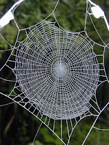
It seems to me that webs consist of several different types of member, which exist within a distinct structural hierarchy. In the first instance there are a series of threads which anchor the web to its surroundings, we shall call these the moorings.

The moorings are connected to the corners of an outer primary frame, which encloses the web. At each corner a secondary frame joins both sides of the outer frame together, but without touching the corner.

A series of radial threads extends from the centre of the web onto the primary and secondary frames. Together these members give the web its overall shape.

A spiral thread winds from the centre of the web towards the outer frames. Unlike those discussed thus far the spiral thread is made of a sticky silk, which is thinner than the other members, and is intended to catch the spider’s prey.

Before we consider how this rather spindly arrangement of threads manages to resist the impact of spider prey, and the force of strong winds, it is worth explaining a key structural principle.

The theory of elasticity dictates that when a load has several different load paths to choose from it will always prefer the one which has the greatest stiffness. In simple terms load is distributed between members according to their stiffness with the stiffest parts attracting the most load.

The importance of this principle may be illustrated by considering what would happen if spider’s designed their webs a little differently. Let us suppose that the hypothetical Institution of Web Safety, were to decree that secondary framing was no longer permitted and therefore radial threads must connect directly to the outer primary framing on all sides. Connecting directly to the primary frame, sounds like a simplification of the structural load-path. That must be good, right?

A further implication of the IWS’s directive would be manifest at the corners of the frame; the radials would now be connected directly to the moorings. Again, that must be a worthwhile safety improvement, because load is directed straight to the point of support.

We can test our theory by imagining a hypothetical fly careering into the web. We want the web to absorb the impact without breaking; that would be bad for the spider’s prospect of lunch.

This means that we want the web to spread the impact force across as many structural members as possible. The more members mobilised to resist the applied load the smaller the load each will carry.

Immediately after the fly strikes the sticky spiral the web’s load-path swings into action. The spiral is connected to lots of radials and begins to share its load. But now something has gone wrong, the load has reached a radial which is connected directly to the moorings. Being connected to the point of support this radial is much stiffer than adjacent radials, which are attached to the outer frame, which has started to flex. Load is immediately attracted out of the radials connected to the outer frame in favour of the stiffer pathway. Soon the radial connected to the mooring is carrying nearly all of the load and is stressed to breaking. Our spider’s lunch is about to escape.

Surprised by the evidence of systemic failure in radial web members the IWS takes the decision to withdraw its directive and reinstates secondary framing, which once again must be connected to the outer frame either side of corners.

Soon an unfortunate fly finds itself bumping into a web with newly reinstated secondary framing. Once again the spiral members spring into action and begin to transfer load into the radials, but this time something different happens. Instead of load being directed straight to the moorings it finds itself being directed into the secondary framing which begins to flex before re-directing load back towards the middle of the outer framing and away from the stiff corners.

The outer framing begins to flex and in doing so starts to engage other radials to which it is connected, before long much of the web is flexing and load sharing is being maximised. On this occasion there is going to be no failure. It looks increasingly like the fly is doomed and the spider will be enjoying lunch.

It seems to me that the web’s structural arrangement is designed to avoid stress concentration. This key feature maximises load spread and minimises the stress in individual members. Another consequence of the redistributive process is that the web becomes less vulnerable to local damage; because load can by-pass those areas.

Thus spider webs have a highly efficient structural form optimised for absorbing impact and for ensuring spiders remain well fed.  

Sunday, November 1, 2020

On Hills, Rocks & Waterfalls

A geological wild goose chase


I recently visited the Queen Elizabeth Forest Park with my family. I had enjoyed the park many times as a child, but I had not been back as an adult. I was very much looking forward to descending into the valley and scrambling up the rocks with my children in order to get a closer view of the waterfall at Camadh Laidir, which lies on Allt a’ Mhangam; a burn that flows into the Forth south of Aberfoyle. In my mind it was going to be just as it was when my younger self made the same journey with my own parents and siblings.

The rock scrambling was indeed all the fun I had hoped it would be. My children took great pleasure leaping from rock to rock occasionally getting their feet wet. Their faces were beaming with excitement as we approached our planned destination. Finally, we sat perched on a large boulder looking down on a pool of foaming water and then up at the picturesque waterfall.

Although almost everything was the same as I had remembered there was one thing that was different this time around. Something, that was in plain sight and was not remotely new. The difference was the fact that this time I had noticed.


At the base of the waterfall there was a distinct line of curvature in the rocks where those above seemed to be slipping smoothly over those below. It was immediately obvious to me that I was looking at a fault in the rock formation. A point were two sections of crust had been forced together and pushed passed each other many millions of years ago. 

It turns out that climbing to the base of the waterfall is not only good fun, but it also affords the opportunity to view a geological feature at close quarters.

A week later we decided to spend Saturday climbing Conic Hill with friends. Although it is not a Munro [a Scottish Hill more than 3,000 feet above sea level], Conic is a scenic location, because it looks down on Loch Lomond and is aligned with the Highland Boundary Fault. As you climb beyond the tree line you can follow the trajectory of the fault to the base of the hill and all the way across Loch Lomond, where the islands of Inchcailloch, Craobh-Innis and Inchmurrin lie on its path.

Thus, climbing Conic is not only an enjoyable hike, but it also provides an excellent opportunity to view a geological feature on a macro scale. 

On reaching Conic’s summit and turning to view our accomplishment from several directions it dawned on me that I recognised the landscape. It seemed familiar.

I suddenly realised that in the distance I was looking towards the Queen Elizabeth Forrest park where I had been the previous week. A most intriguing thought then entered my mind. Could it be that the fault I had been looking at close up the week before was somehow related to the fault that I could now see cutting across the landscape in the opposite direction?

On returning home I consulted google maps [other map services are available]. To my great delight I found that I could draw a straight line across Loch Lomond, through Conic Hill and straight to towards Aberfoyle; the small village located just to the south of the waterfall. Frustratingly I required a computer monitor roughly twice the size of the one I have to pick out the precise location of the waterfall when viewing at a macro scale.


Never-the-less I had perhaps discovered that the falls at Camadh Laidir were geologically connected to the Highland boundary fault. Discovered for myself that is; I am quite sure that if correct Geologists would have known this fact for a great many years. 

Undeterred by this small detail Google map’s apparent conformation of my discovery brought me considerable delight, because I had spotted the link for myself. In the moment I was perfectly happy to overlook the fact that perhaps this was something I might have known already had I paid more attention in geology class 25 years ago.

After some further time invested in squinting at online maps [belonging to the Ordnance Survey and British Geological Survey] to pick out the watercourse profile at Camadh Laidir, I have reached the conclusion that the waterfall is indeed located on a fault, but one just a little to the north of the actual Highland Boundary fault. Are they related; I really hope so, but I need a proper Geologist to tell me.

Even if they are not strictly related my geological adventure, which was quite unintended, is a reminder that, owing to the four major faults that divide its foundations, Scotland has an incredibly diverse geology squashed into its rather tiny land mass. Is it any wonder that the origins of the subject lie within its boundaries.

Incidentally, for those unacquainted with a civil engineering education geology is one of those subjects that is bolted on to Statics, Materials & Fluid Mechanics. In theory we were supposed to learn something about the make-up and behaviour of the ground, as we could one day be asked to tunnel through it, anchor a building or bridge to it or perhaps restrain it from moving.

It follows that the endearing story of my rather amateur geological wild goose chase counts as an acceptable topic for a blog about Structural Engineering. It has to because I need to tell someone and my family and friends aren’t interested. 

Sunday, September 27, 2020

On Stegosaurus

The original idea for this post was to show an animal’s skeletal structure and explain how it works. I have chosen to do this using a stegosaurus skeleton for two reasons. 

Firstly, this blog is going to be a bit speculative, because I don’t know anything about animals or their skeletons. In the event that a biologist or anatomist finds him or herself reading this blog there is a high probability I shall be politely informed that I don’t know anything. Based on this I figured that my best form of defence would be to choose an animal for which there are no living examples. This way I can argue that since there are no living examples what said animalist thinks they know is mere speculation. No-one can prove otherwise.

Secondly, stegosaurus is a dinosaur and dinosaurs are cool, every kid knows that. Of course I could have chosen T-rex or triceratops, but I think those are the obvious choices and I happen to like stegosaurus so that’s what I’ve chosen.  Here goes….

It seams to me that the spine of an animal, which supports its head and tail are analogous to a thin flexible truss; in fact a special type called a vierendeel truss. To explain this I am going to need to make a few assumptions. Self-evidently all animals walk, run, jump, climb and so forth. Okay, I don’t know whether the last two are true of Stegosaurs, but neither do you. See how effective that defence is? Anyway, movement gets a bit too complex for my stated aim of explaining how skeletal structures work. With that in mind I am going to assume, for the purposes of this blog post, that we have a stationary stegosaurus standing on all four legs.


Based on this the first observation we shall make concerns the legs. The fore-limbs, compared to the hind-limbs, are rarely small, however they are still stocky and have the appearance of being load bearing. The larger hind-limbs and pelvis are larger and would appear designed to carry greater load. This corresponds with the head and neck being rather small when compared to the size and bulk of the hind-quarters and tail.

The stegosaurus’ spine bridges between the two sets of legs and cantilevers beyond them at both ends in order to carry the neck and tail. To understand the structural implications of this arrangement we must first learn something about bending moments.

A bending moment is a turning force whose magnitude is the product of force (or weight) multiplied by the distance (known as the lever arm) to the nearest point of support. The greater the distance to a support; the greater the bending moment.

Consider if you will the following thought experiment. Supposing the stegosaurus’ fore-limbs were located at the end of its nose. I know that’s daft, but run with it. The distance between the nose and its legs is zero therefore no matter how heavy the nose the resulting bending moment is zero.

Now suppose the fore-limbs are located at the back of its head. The bending moment has increased from zero in proportion to the length of its head. I hope you can see where I am going with this. Now suppose the fore-limbs are back where they should be attached to the shoulders. The bending moment has now increased in proportion to the length of a stegosaurus neck and head.

If we were to portray the magnitude of the bending force graphically it would look like a triangle, being zero at the nose and increasing to a maximal point where the legs meet the shoulders. We could repeat the same process starting from the tail. The bending shape would be the same, though the height of the triangle would be bigger because the tail is longer and heavier.

We are now left with the bit in the middle, we need to join the two triangles together. Of course the  body of the stegosaur is somehow attached to the spine (I told you I am not an animalist). We’ll get back to that subject later, but for now we will simply note that the weight of the body must pull down on the spine. It follows that a line depicting the bending moment will join the two triangles, by sagging in middle. It might look a bit like the diagram below. 


The interesting bit; also the bit where I might start to get into trouble; is how the spine resists these bending forces.

The first thing we notice about a stegosaur spine is, like most spines, the odd shape of the vertebrae, which is distinguished by three parts, at least to my eye. There is the oval shaped portion located at the anterior. The lower part is of bone and the upper part has a hole where the spinal cord would be. 

The second feature is the piece of bone that projects vertically from the middle of the vertebra to form the posterior.  This is where the ligaments and muscles of the back are connected to the vertebrae.

The third feature is the two transverse projections; one either side of the vertebrae. These are where muscles and ligaments attach to the spine and are also the points from which the ribs are articulated. The fossil stegosaurus vertebrae pictured below is quite tall and for reasons that will become clear is postulated to be from the lower part of the back.

When the vertebrae are aligned in a row, as they would be to form a spine, they start to resemble a truss with a lower chord of bone and an upper chord of ligament and muscle. You have to imagine the muscle and ligament joining the vertical projections together, as self-evidently they haven’t been fossilised. The internal members of the truss are formed by the bone surrounding the spinal cord and the projection that extends from it. There are of course no diagonal members and that is why the resemblance is to a vierendeel truss.


For this information to be of use we now need to describe how a truss works. We shall begin by considering a beam, which is altogether a simpler and humbler form than the truss. 

If a beam spans between two supports, one at either side, it will deflect in the direction of the bending force to form a curve. As the beam deflects the outer edge of the curve is stretched and is evidently in tension. Conversely the inside edge is squashed and must be in tension. The centre of the beam, known as the neutral axis is neither in compression nor tension; it is at rest.

If we apply the same logic to a truss the outer chord of the truss carries a tensile force and the inner chord carries compression. The internal members of the truss transfer load between the outer and inner chords. 

In the case of our stegosaur based truss the ligaments and muscle at the posterior are ideal for carrying tension and the boney part at the anterior is ideal for resisting compression. This is remarkably good luck, because as nature would have it, the bending moments imparted by the tail and neck of the stegosaur, as shown in our earlier diagram, impart tension on the posterior side and compression on the anterior.

If that is not remarkable enough the depth of the vertebrae increase towards the hind limbs to match the increasing magnitude of the bending forces. Nature has actually fine tuned the size and shape of the vertebrae so that the resulting truss matches the shape of the bending forces to which they are subject.

Having made this observation it is tempting to end this post satisfied that our work is complete, but I am not quite ready to do that. There is one more thing that is just too interesting not to pass comment. I also noted earlier in the post that I would return to this subject.

It is not lost on me that the stegosaur spine has a very distinct curve, which given the apparent fine tuning of the vertebrae, cannot be without reason. Based on that it is, I think, worth a further speculation. 

It strikes me when looking at the bulk of a stegosaur’s body, how is that great big, heavy fleshy part of the animal supported from the spine. Presumably it somehow hangs? I imagine the animal’s flank muscles, perhaps reinforced by the ribcage, are responsible for transferring the load.

It then strikes me that an arch is a rather efficient way of supporting the load and transferring it to the legs. There is of course a potential issue with this load path. Arches generally have large abutments whose purpose is to resist the lateral thrusts generated at the base of an arch and thus prevent it from spreading. It is these same thrusts that make it so difficult to build a house of cards. Of course stegosaurus have no abutments.

There is a potential solution, which is to be found in the form of a bow string arch. Sometimes when there is no opportunity to provide bridge abutments the engineer will instead join the arch supports together with a tie member. This works by causing the two sides of the arch to pull against each other. Since the pull is equal and opposite equilibrium is maintained and the arch is prevented from spreading.

My final speculation is therefore that the stegosaurus’ sternum and chest muscles provide a tie, which form’s a bow string truss made of meat and bone.

Now I can finish the post and wait to be shot down by people that know what they’re talking about. I shall be lying in wait with my pre-prepared speculation defence.

On Ice Shelf Cracking

Tension Cracks in the Brunt Ice Shelf Yesterday the BBC news website published images showing a large section of the Brunt ice shelf in Ant...