Showing posts with label equilibrium. Show all posts

Sunday, August 15, 2021

On Pentre Ifan

Some observations about Dolmen


This evening I watched a documentary presented by Alice Roberts. I don’t think I have watched a programme presented by Dr Roberts that hasn’t been interesting, and this one was no different, except that the most interesting thing wasn’t strictly the topic. The documentary was about the bluestones of stonehenge, but it strayed ever so slightly to Pentre Ifan in Wales were I was introduced to Dolmens. These are Neolithic structures, which predate Stonehenge. There are lots of them around the world and some are thought to be around 7,000 years old. The Dolmen at Pentre Ifan is a spectacular example, whose massive capstone appears to float above the tips of three standing stones. I expect that’s why I noticed it and why Alice Roberts chose that example.


Archaeologists believe that Dolmens were ancestral tombs, because scattered human remains are often found between the standing stones. Some also believe that they were originally buried beneath a mound of earth or smaller stones.

Interesting as these conjectures are I can’t get past the graceful form of the structure. I suspect that archaeologists, for the most part, take for granted that the monument stands, while going to great lengths to try and understand how it got there and how it was built. I think I understand why this is, but there is a certain irony that for such an old object so much more effort is expended on the temporal than the permanent [1].

To me the fact that Pentre Ifan is standing at all is more interesting and is the subject of this post. Maybe on another occasion I’ll fall in to line with everyone else and have a go at speculating how such structures are built, but not today.

I should of course pause to note that I have never seen a Dolmen in person, nor do I really know anything about them, other than tonight’s brief introduction. I am keen to remedy that and will aim to visit some examples when the covid-19 lock-down has ended, however that isn’t going to stop me from donning my engineering hat and doing some speculation of my own. I shall be doing so based on a few images I have pulled off the internet; what could possibly go wrong?

I am going to start with the assumption that the stones are igneous rocks, because they have that appearance and because there are outcrops in the the relevant part of Wales. This ought to make the rock relatively strong; though like any rock it will be brittle and weak in tension.

There is evidence of horizontal fractures in the capping stone and equivalent vertical features in the standing stones. Structurally this is not a terribly efficient arrangement. A stronger arrangement would be to align planes of weakness in the standing stones horizontally so that they are squashed together. For the capping stone it would have been better to align them vertically so as to avoid separation due to shear flow generated by bending forces.

I suspect that this was not done, because creating the great slabs of stone required cleaving them from the parent rock by exploiting the noted weaknesses. Without them stone-age workmen would have had difficulty creating such slabs with primitive tools.

The next thing I notice is that the capping stone appears to be fatter at one end than the other and that the soffit appears to have been cleaved as it progresses towards the thin end. I suspect that it was not originally so.

The fat end is supported by two standing stones, while the thin end is carried by one. In the short axis the fat end of the capping stone can bridge laterally between two close supports. It can possibly do this in direct shear and without inducing bending.

Conversely, in the longitudinal direction the capping stone must span almost 5 meters between the single and double support. This almost certainly results in it experiencing bending. As has been seen in prior posts bending causes the top surface of a beam to experience compression and the soffit to experience tension. 

In order for this to happen a beam will also experience a laminar shear flow in the horizontal direction. This can be understood by imagining a beam divided into horizontal slices. For tension to be experienced on the soffit while compression is experienced on top it is necessary for the imaginary slices to slip past each other.

The consequence of these actions appears to be evident in the structure. Since stone does not deal well with tension it is inevitable that small cracks must have developed in the soffit. There would also have been lateral movement along the rock’s natural horizontal weaknesses. It is conceivable that together these effects led to the soffit spalling, however it is more likely that they were abetted by other effects too.


Rainwater will have soaked through the top surface of the slab and migrated under gravity to the soffit. While moisture would evaporate quickly from the top the soffit would remain in the shade helping to keep the stone damp and wet. Persistent dampness will have weakened the rock structure and freeze thaw action would have exploited the many small cracks and natural weaknesses. Eventually the fractured rock would spall until it arrived at a horizontal plane of weakness whereupon the process would start again.

Perhaps another aggravating factor would be expansion and contraction due to the cycle of heating and cooling. Since only the top surface is exposed to the sun there is likely to be a thermal gradient in the capping stone as it warms. During the day the top of the stone would expand relative to the soffit and thereby start to close some of the soffit cracks. Conversely, during the night it would start to contract and thereby re-open the soffit cracks. Thus, by repetition the soffit would slowly be fatigued and further cracks induced.

When considering thermal effects it is worth noting that having only three small points of contact between the capping and standing stones is probably beneficial, because the soffit is free to articulate. More severe cracking would be much more likely if the top surface were free to expand and contract while the soffit was held in place by more restrictive contact. 

It would therefore seem that there is a good explanation as to why the capping stone is fatter at one end than the other, and all else being equal, by what mechanism it will eventually fail.


The standing stones appear to carry the capping stone effortlessly. The fact that they do so with such small points of contact would suggest the compressive strength of the stone must be relatively high. That said, it is assumed that the contact surfaces could not have been prepared to a modern standard and therefore the distribution of load will not be entirely even. This will have allowed load concentrations to be formed which may over time pry and fracture the rock locally.

This is important because compression in the standing stones will cause lateral bursting forces to develop due to passion’s ratio [this is another concept we have seen before]. Within the body of the stone compressive stress is generally low and therefore the bursting forces have little effect, however where load is concentrated stresses are higher. If such stresses coincide with a vertical plane of weakness it could encourage the bursting forces to form a split in the rock. As with the capping stones this could be exacerbated, either by moisture penetration, or by bending induced by one side of the rock being warmed faster than the other. There does seem to be some evidence of such processes at work on the surface of the standing stones.

Another facet of the pictured Dolmen is how it maintains lateral stability. It is self evident that there is no rotational resistance at the junctions between the capping stone and its supports, therefore we must conclude that the standing stones must cantilever from ground level. Since the capping stone bears heavily upon them there will be sufficient friction generated to share lateral load between the standing stones according to their stiffness.

Lateral loads would come from the wind and to a lesser extent thermal effects. There also appears to be a slight incline to the capping stone, which would imply there is a resultant lateral load, due to the stone’s self-weight, to be resisted.

Something else that is structurally relevant, though I am unsure whether it was intended, is the orientation of the standing stones. The two stones at one end are orientated perpendicular to the single stone at the other. Strength being proportional to the cube of depth this arrangement presents the full depth of at least one stone in each orthogonal direction, thus maximising cantilever action in both.

It is also interesting that the end supported by two stones is aligned with the noted incline to the caping stone, thus maximising resistance to the permanent lateral load. The possibility that this was intended is intriguing.

A different explanation would be that since one end of the structure has two supports, and the other just one, there could have been differential settlement. Assuming this were the case the narrow supports would again have been beneficial, because they would have allowed the capping stone to rotate and find a new point of equilibrium. Alternatively, more substantial supports would have likely led to fracture. I have no idea what the bearing strata beneath the standing stones is like, but in the absence of further evidence the mechanism for differential settlement seems plausible.

Of course it is also possible that the fractured soffit could have contributed to creating the observed incline too.

While the depth of embedment of the standing stones is not clear from viewing the surface it seems reasonable to assume that it must be substantial to ensure there is sufficient passive resistance to prevent overturning or sliding of the stones. In a uniform soil it would also be reasonable to assume that bearing pressure would increase with depth.

On paper it is perhaps possible that the stones could be mounted near the ground surface with stability being maintained by their shear size and mass. In the real world this does not seem plausible as the surface of the ground is prone to become waterlogged, there is also the possibility of frost action. Either of these effects could be sufficient to topple the stones.

Two further practical matters exist. Firstly, a shallow footing would be vulnerable to digging near the base when bones were to be buried. 

Secondly, and perhaps more importantly, the processes of standing large stones on end without a crane, or other modern equipment, would seem to make it necessary to tip them into a hole. If said hole were then packed tight with backfill it would lock the stones in place allowing them to behave as cantilevers.

Here I run the risk of getting into the question of how the stones were erected and I said I wasn’t going to do that. I best stop here.


[1] I base this thought on working with a few archaeologists and the number of documentaries there are about erecting Stonehenge, rather than any proper search of the archaeological literature.


Sunday, August 8, 2021

On Pendentives

A tale of two domes

Perhaps two of the most important domes from antiquity are those belonging to the Pantheon in Rome and the Hagia Sofia of Istanbul. Although the latter is to be found in modern day Turkey, it is of course from the era of Byzantine rule in Constantinople and is therefore of Roman origin.


From their outward appearance the two domes would appear to be similar, indeed how different can the construction of a dome be? Further inquiry would reveal that the materials used to construct the two domes are different. The Pantheon is made of unreinforced concrete, while the Hagia Sofia’s dome is of masonry. Indeed the Pantheon remains the world’s largest unreinforced concrete dome to this day.


This difference is interesting, but in my view is not fundamental to the way in which these two revolutionary structures work. I am perfectly aware of the Pantheon’s oculus, its coffered soffit, the variation in concrete mix over its height, all of which were designed to save weight. These are important details, which are both interesting and worthy of study, maybe I will write about them in some future point, however they are not directly relevant to the subject of this post.

The first thing to note is that classical domes, like later gothic structures, are what I would describe as gravitational or compressive equilibrium structures. That is to say that their structural adequacy is dependent on their shape and not on materials science. This is possible because actual stresses are compressive and sufficiently low that, providing equilibrium is maintained, material strength is unimportant. This makes sense because materials science, at least in the modern sense of stresses and strains, did not exist when they were built. 

Those familiar with the structures in question will no doubt be aware of known cracking in both domes, which might be taken to suggest that there is in fact some material science going on, however as we shall see this is not the case.

To understand the primary difference between the Pantheon and Hagia Sofia, perhaps it is first necessary to explain how a generic dome works. In section domes behave in a similar manner to arches, because their curved profile exerts both vertical and lateral thrust at the seating[1]. Domes are of course unlike arches in the sense that they are 3D structures. This means that the aforementioned vertical thrusts are expressed as compressive meridional stresses extending from the crown of the dome to it’s base. The lateral thrusts push outwards in all directions generating a circumferential or hoop stress that cause domes to spread. It is the way in which the meridional and circumferential stresses are resisted that makes the difference.

Like barrel vaulted structures from the classical period of history the Pantheon is supported on heavy walls that follow the profile of the roof structure, in this case a cylinder, in order to buttress the roof against spreading. Some descriptions I have read speculate a stepped thickening observed at the dome’s base is designed to provide a circumferential tie. Maybe their authors have done more research than me and have data to support this view, however I am disinclined to adopt it based solely on my own intuition that the tensile capacity of concrete, albeit Roman concrete, is too low. Also, if tension were present it would imply materials science is at work to provide the required equilibrium, which is philosophically less satisfying.

It occurs to me that a more elegant solution, which maintains the idea of gravitational equilibrium, would be one where the purpose of the steps was to increase weight at the head of the supporting wall in order to push the dome’s thrust line back into the supporting walls. In essence it would behave, at least in my estimation, like the pinnacle atop a flying buttress.


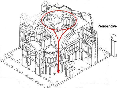
The dome of the Hagia Sofia is different. It does not find support from heavy buttress walls. Rather it straddles the four corners of a vast open space into which light and air may flood. In character it is a medieval structure whose load paths concentrate the dome’s weight into a carefully defined masonry skeleton. The invention that makes this possible are the inverted triangular masonry panels, known as pendentives, that are located over the four supporting piers. As they spread outwards from their apex a series of four arches are formed on the dome’s perimeter. Together these elements funnel load into the supporting piers where the in plane arch thrusts are buttressed.

It is evident however that there remains unbalanced thrusts perpendicular to the apex of each pendentive arch. Equilibrium is restored by hemispherical domes that lean in the opposite direction to the dome’s thrust in one direction and buttresses in the other.


And so it is that the dome at Hagia Sofia represents a transition between heavy buttress walls and gothic cathedrals of the later medieval period, whose structures had a more clearly defined order of primary and secondary elements and a more sophisticated understanding of load paths.

Now, to the aforementioned cracks in both domes. Many seasoned observers hold the view that these are the result of past seismic events and differential settlements. Indeed the original dome at Hagia Sofia is known to have collapsed during an earthquake leading to the present cupola being constructed with a higher profile in order to reduce the magnitude of lateral thrusts. 

Nevertheless it would appear that in spite of movement to both structures gravitational equilibrium has been restored. They remain stable, or at the very least, are moving very slowly.


[1] For further information I have written several prior posts relating to the behaviour arch structures.

Sunday, July 11, 2021

On San Petronio

Gravitational equilibrium & the square cube law


‘Gulliver’s Travels’ is a classic of English Literature written by Jonathan Swift in 1726. It is intended to be a satire of human nature and ‘travellers’ tales’. In the book its protagonist visits the fictional countries of Lilliput and Brobdingnag. The citizens of the former are 12 times smaller than Gulliver and in the latter they are 12 times bigger.

Of course every reader of the book knows that Lilliput and Bribdingnag are fictional, but perhaps fewer might realise that they are necessarily fiction in any possible world that follows the same physical laws as our own. The reason for this is described by the square cube law, which was first attributed to Galileo.

According to this law the size of things cannot be indefinitely scaled up, because the physical properties of objects change as they increase in size. Consider a cube with sides one unit long. If we were to double the length of each side then the surface area of each face will increase from 1 to 4 units. The volume of the cube, and by extension the quantity of stuff from which it is made, increases from 1 to 8 units i.e. doubling the linear dimensions causes the surface area to be squared and the volume of stuff to be cubed.

In other words the rate at which the volume and weight of an object increase with size is greater than the rate at which its linear dimensions and surface area increase.


Conversely, the strength of things, normally expressed as a limiting stress, is independent of size
[1]. It follows that as things become larger, while retaining their original proportions, they will eventually reach a point where they can no longer support their own weight. This places an upper limit on how big things, including people, can get.

This is a vexing problem for modern day architectural students, who are surprised to learn that the model they have spent hours building does not prove that the structural gymnastics their design requires are viable in the real world.

There is of course an exception to the square cube law, though not a true exception. The square cube law does not cease to work, rather it is not discernible within the normal range of scaling for certain objects.

An example of such an object from the natural world would be a mountain. An equivalent structure form the man-made world would be a pyramid. Both structures come from a class of things that share three key ingredients. Firstly, they are both made of stone, which is a natural material with a very high compressive strength and low tensile strength. Secondly, they are both compression structures that assiduously avoid tension. Thirdly, they are stocky and solid structures. Not solid in the sense that they are strong, though that is indeed true, but solid in the sense that they are not hollow. The implication of being stocky and solid is that they are not prone to buckle, as a slender or thin walled structure is. A second implication of stockiness is a large cross-section, which implies low stress.

These then are the ingredients for subverting Galileo’s square cube law and within the class of things which have these ingredients there is a group of structures that does so with a style and panache that is difficult to surpass. They laugh in the face of the square cube law.

I am of course talking about gothic structures; those great stone cathedrals of the late medieval period with their quadripartite vaults and flying buttresses. I am often asked, mainly by my dad, how it was that medieval masons created such structures in the absence of modern structural theory. The stock answer is that they used rules of thumb, but for me there has to be more to it than that.

How on earth did they manage to design structures, using rules of thumb, that modern analysis shows us to have near perfect proportions. Rules of thumb are intended to apply generally, but must necessarily be derived from the particular. The further a design departs from the particular the less useful a rule of thumb is. 

Gothic structures do have similarities, but there is also great variety in their design, which ought to make rules of thumb less helpful.

Perhaps the answer to this dilemma is to be found in a process of trial and error. While there was undoubtedly a role for trial and error I am not convinced that it played a central role, at least not in the commonly understood sense. I hold this view for several reasons:

Firstly, most cathedrals took hundreds of years to build and though master masons may have worked on several, they would not, in their own lifespan, have time to learn all the necessary forms by trial and error. This brings us back to rules of thumb. Secondly, while there is evidence of design evolution over time there is relatively little evidence of major failures, which is odd given the innovative, and often spectacular, designs adopted. Furthermore, when known failures occurred they were often, though not always, associated with abnormal events like earthquakes or phenomena external to the structure like differential settlement.

We therefore have much evidence of trying daring new things, but scant recorded evidence of failure [2]. This is not entirely a surprise, because cathedrals are expensive and their proprietors were not stupid. Master masons would not have been in charge for long if their structures kept collapsing.

To find a satisfactory explanation I think we need to return to the square cube law. If a structure could be designed to subvert the square cube law then a successful pattern would be successful at any scale. It follows that if you could demonstrate a particular form of structure would stand using a small model made of wood then it would also stand if it was scaled up to full size. 

I do not know whether masons understood that they were subverting the square cube law. I suspect that they didn’t, but I do think that they understood perfectly well the load-paths and principles that were necessary to keep a stone structure in equilibrium. I think they fully understood that tension was the enemy and that gravity must be harnessed to maintain compression in all parts of the structure. 

They were specifically designing structures to achieve gravitational equilibrium and they were doing it by experimentation with scale models. They then used rules of thumb, derived from these models, to scale up their findings to full size structures.


Happily for the masons this methodology was just perfect for avoiding the square cube law, whether they knew it or not, and in this way spectacular and innovative designs could be realised without needing to know anything about materials science, stresses or strains.

While this theory involves a heavy dose of speculation it is not without evidential support. For example, we know that Antonio Vicenzo the designer of San Petronio church in Bologna commissioned a model of brick and plaster at circa one eighth scale. It was around 19m long and 6m high. I expect that it was used to convey the design to its proprietors, but I don’t think it is too great a leap to posit that it might also have played a role in the church’s structural design.


[1] I accept that all bets are off at the atomic scale, but we don’t normally consider atomic forces when designing building structures, bridges and the like.

[2] I know that absence of evidence is not evidence of absence, nevertheless evidence is sometimes notable by its absence, particularly when there might be a reasonable expectation to find some.


Sunday, June 27, 2021

On Lunes & Cracks

Conserving St Peter’s Basilica


The dome of St Peter’s Basilica in Rome is one of the most recognised structures in the world. It was completed around 1590 and was conceived by the genius Michelangelo. There are many reasons why it is special structure, but perhaps the most important is amongst the least well known.

By around 1680 cracks were being reported in the dome, which unsurprisingly caused some to question its safety. Concerns were exacerbated following an earthquake in 1730. Meridional cracking, associated with a dome’s tendency to spread at the base, was well known in the sixteenth century and therefore, following a detailed investigation, a recommendation was made to supplement the existing wrought iron hoops, which were intended to prevent spreading, with three or four more.


It would seem that the Vatican had travelled a distance since Galileo’s heresy trial and the incumbent Pope Benedict XIV, unlike many designers and practitioners of the day, was impressed by the progress made by scientists and mathematicians of the day. He therefore commissioned three of them; Thomas Seur, Francois Jacquier & Roggiero Boscovich to examine the subject. The publication of their findings in 1743 was a seminal moment for Structural Engineering, because they had based their conclusions on a mathematical analysis of the dome. It was the first known occasion when this was done in any meaningful way. Their approach included a model of the dome’s weight, its materials and two different behavioural scenario’s. The method they adopted for combining this information would today be called ‘virtual work’.

They concluded that the existing iron rings embedded within the dome were insufficient to prevent spreading and that the dome would collapse. They therefore proceeded to calculate the number and proportions of additional rings. This was of course a safe recommendation, however it overlooked the rather important fact that the dome had not in fact collapsed and was very much still standing.

Though they were three of the smartest mathematicians of their day they had made the same basic error that almost every graduate engineer makes at some point. They had placed their confidence in their model over what they could see with their eyes. One of the most important truisms of structural engineering is that a structure will remain in place until it has exhausted every possible means of standing. Consequently, if a mathematical model says a structure will collapse, but it stubbornly refuses to do so, then one is obliged to conclude that the model is wrong and not reality.

The presiding committee responsible for the church’s upkeep did what committees often do. They ignored the expert report and continued to monitor the structure. Benedict was also dissatisfied, but wished to persevere with a scientific approach. He commissioned a new study by a different expert Giovanni Poleni. 

Poleni criticised aspects of the first report and tackled the problem with a different approach. While he conceived his own mathematical model, Poleni was also aware of Robert Hooke’s work on the stability of arches, which is described in an earlier post [On Balloons, Chains and Arches]. He therefore imagined the dome to be split into a series of lunes each of which rested against an opposing lune on the other side of the dome. He then used a physical model to demonstrate that the line of thrust for a pair of lunes lay within the depth of their cross section and would therefore meet Hooke’s criteria for a stable arch. By this reasoning the whole dome, being a series of balanced lunes, would be stable in spite of its meridional cracks.

Nevertheless, Poleni also recommended four additional wrought iron hoops, which were installed in 1744. A further hoop was added in 1747, when it was discovered that one of the originals had in fact fractured.

While the application of mathematics to structural engineering problems, which was pioneered by Seur, Jacquier and Roggiero, would prove successful in the long run it is not difficult to see why it was unsuccessful to begin with. 

While mathematicians and scientists had been publishing treatise on engineering subjects from the early eighteenth century, architects and engineers of the day were unacquainted with mathematical argument and treatise were therefore largely ignored.

A second, and perhaps more significant issue, was the relative maturity of the respective disciplines. Eighteenth century mathematical models, though brilliant in their conception, were no match for 1,000 years of engineering experience, which had refined and optimised known structural forms about as much as it was possible. The only conceivable  advantage for science would be for the conception of structures for which there was no precedent.

This dichotomy caused a divergence in engineering practise between Britain and its European neighbours. While France and Germany forged ahead with academic schools of engineering Britain largely adopted an empirical approach. Unsurprisingly the continental Europeans produced more impressive academic works, however Britain prospered with its empirical approach, which produced closer alignment with the real world and therefore greater efficiency.

Britain’s engineers did not dismiss theoretical works, because they were less intelligent or less capable. They simply knew that the best academic theories of the day could not get close to matching the empirical approach they were pioneering.

There is a lesson in this for the modern engineer. Modern codes of practise are becoming increasingly academic and less practical. It is not clear to this engineer that the additional effort required to use them yields a justifiable benefit. I am also quite certain that as in the eighteenth century some modern methods are less efficient than the empirical methods they have replaced.

In some circles our profession needs to rediscover the once obvious truth that a theory, which does not match past empirical experience, is not a good theory.....particularly when it is more complex to use than its predecessor.


Sunday, May 23, 2021

On Gravity Glue

The importance of equilibrium


Michael Grab is an artist with a website called Gravity Glue. I think its a great title, which describes perfectly his stone balancing art work. It’s also a really good description for the concept of equilibrium, which is probably the most important principle in structural engineering. For unless there is equilibrium none of the other concepts much matter.

If you have not come across stone balancing before it is worth looking at Gravity Glue. The essential idea is to stack a pile of rocks one on top of the other without them toppling. The key is to find stones of different shapes and sizes and to join them in a way that intuitively seems unstable. There is nothing holding the stack of rocks together other than gravity acting on their weight and pushing them together; hence the term gravity glue. Finding precisely the right position and angle to stack each rock is tricky. It takes experience and patience to find the point of balance.


I don’t just like Michael Grab’s stone balancing, because of the engineering parallel, but also because the arrangements he creates are attractive in their own right. Some of this is attributable to the visual backdrops, but it is also more than that. His arrangements are clever and visually interesting. I too could balance some rocks on top of each other, but I don’t think the result would come close to what Grab achieves. He manages to surprise our innate sense of balance and to challenge our perception of what ought to be stable. I think it is these qualities, which provide the visual interest.

Equilibrium is simply the term that engineers use to describe a structure that is balanced. In order for balance to be achieved two criteria must be satisfied. Firstly, the magnitude and direction of all the forces acting on and within the structure must add up to zero i.e. for every force acting upwards there must be one of equal magnitude acting downwards. Similarly, for every force acting left there must be one of equal magnitude acting right. If this condition is not satisfied the structure will not be stable and will move in the direction of the unbalanced force. For example, if the force acting to the left is greater than that acting to the right then the structure will move to the left.

The second condition of equilibrium is that the moments resulting from the forces acting on a structure must also add up to zero. Moment is a turning action, which is the product of a force and its distance from the point of rotation. For this reason a small force acting at a large distance can generate the same moment, as a large force acting at a short distance. This abstract concept is easily illustrated by considering an adult and a child on a see-saw. To find the point of balance the adult must move closer to the fulcrum of the see-saw than the child. Conversely, if the adult sits too close to the end of the see-saw the child will be propelled upwards and the adult downwards. It follows that if the forces acting on a structure are balanced, but the moments are not, then the structure will topple in the direction of the unbalanced moment.

Applying these principles to stone balancing the forces acting on a stack of rocks are the self weights of the stones due to gravity. The first of the two equilibrium conditions is satisfied  by default. Since the stack is supported on the ground the ground will push back on the stones with an equal an opposite force. If it did not then the rocks would either sink into the ground or they would take off. The tricky bit is therefore balancing the moments.


Since the rocks are of different sizes and have unusual shapes their centre of gravity [the axis through which their weight acts] does not act through the point where the rock above is in contact with the rock below. An overturning moment is therefore generated. To balance the overturning moment the rock above must be rotated to move its centre of gravity towards the point of contact or the next rock up must be placed such that it generates a restoring moment in the other direction. As long as one of these two options are selected then the stack will be in equilibrium and will remain stable.

That said, if the weather were to turn and a strong wind were to blow then an additional external overturning moment would be generated. If this moment exceeds the effect of the stones self weight then the stones will topple. This thought introduces an interesting subtlety to the concept of equilibrium.

A structure can be in a state of equilibrium, however if that equilibrium is vulnerable to disturbance by an external action, particularly a small disturbance, then it is said to be in a state of unstable equilibrium. This is precisely the reason why stone balancing is difficult and requires such patience. The arrangements are invariably in a state of unstable equilibrium and in many cases the stability of the lower stones relies on the presence of the upper stones. I imagine that it must require octopus-like qualities to hold the lower stones in precisely the right place while the upper ones are added.

It is precisely this unstable form of equilibrium, which makes Michael Grab’s creations so visually interesting. Much like trying to stand a pencil on its end it does not seem possible to find the ‘Goldilocks point’ were there is neither too much over-turning moment in one direction nor in the other. Herein lies the patients and the skill.


Of course, while it creates an interesting work of art, unstable equilibrium is not at all desirable in buildings and bridges. It is self-evident that you want such structures to be resilient to disturbance so that they do not easily become unstable. Indeed this is a key structural design principle.

This does not stop an engineer from appreciating Michael Grab’s gravity glue. I would suggest it enhances your appreciation of his art.


Sunday, May 16, 2021

On Gothic Cathedrals [yet again]

Flying Buttresses 


The flying buttress is synonymous with gothic cathedrals. It moves their structural skeleton out with the building envelope and exposes it to view. It is probably for this reason that it is readily identifiable as one of the defining features of gothic design.

The name flying buttress is also interesting, because if they were invented today we might simply have called them props. The term flying buttress is, I think, a reflection of the history and development of masonry structures.

As we have learned in prior blog posts, early barrel vaulted roofs required thick heavy walls to resist the lateral thrusts, which result from the vaults’ tendency to spread under the influence of their own weight. It was possible to obviate the need for heavy wall construction by concentrating these thrusts using ribbed vaults. This meant that the outer walls need only be reinforced with localised buttresses.

This was all well and good if the church had only a nave, however if there were aisles either side, or additional cloisters, then in order to avoid being in the way the buttresses had to be moved farther away from the nave. This led directly to a requirement for masonry props to ‘fly’ from the nave, over the aisles, and onto external buttresses. 

The flying buttress must resist three different types of loading. In the first instance it must resist its own self weight. It does this by forming a relatively flat arch, just like a segmental arched bridge. The vertical weight of the arch is supported on one side by the nave and on the other by the buttress. The lateral arch thrust is resisted by pushing back against the nave vaulting and against the external buttress. The thrust produced by the nave vaulting is much larger than that produced by the self-weight of the arch and therefore both the nave and the external buttresses can readily accept this load.


Of course, the thrust produced by the nave vaults is the second form of loading to be resisted. Unlike the curved load-path from the self-weight of the flying buttresses this load-path is essentially applied in a straight line, which is probably why the top surface of many flying buttresses is linear and not curved like their soffit.

There are two ways in which the nave thrusts may cause the external buttresses to fail. Firstly, they might rotate about their base due to the thrust being applied at their head. This would be an overturning or toppling failure. Providing there is sufficient mass in the buttress to provide a restoring force overturning will not occur. This is primarily a question of geometry.

The second potential mode of failure is a line of shear extending from the flying buttress to the outside face of the external buttress. In this scenario the top of the buttress is simply pushed laterally relative to the masonry below. To prevent this from happening most buttresses have a large pinnacle, whose weight squashes the shear surfaces together in order to prevent a crack plane from forming. It is in effect the application of a pre-stress, much like that which was encountered in a prior post about gothic window tracery.

The final type of loading to be resisted is wind load. Most cathedrals have a large wooden roof located above the masonry vaults. Without flying buttresses to transfer load from the base of the roof into the external buttresses the wind would generate an unacceptable thrust at the head of the nave walls. There is also a view that the weight of large timber roofs would be too great for timber ties to prevent them from spreading and consequently the flying buttresses must provide a load-path for restraint to roof spreading as well as a route for transferring wind load.

It is the requirement to provide restraint to the timber roof, which is responsible for the presence of high level flying buttresses located above those which prop the nave vaults. 

Something else which is interesting about flying buttresses is how load is actually transferred into them. This is not a trivial question. It is perhaps a statement of the obvious to say that flying buttresses are located outside the nave, while the vaults are located inside. What is perhaps less obvious is how load transfers from one into the other.

The flying buttresses are actually located just above the level at which the vaults are sprung on the inside. This is done to help facilitate lateral load transfer.

The masonry walls and piers in a cathedral are not normally solid, as you might suppose, and neither are the vault conoids. They are generally formed of dressed stone either side of a rubble-mortar infill. Medieval masons did not trust the rubble infill to transfer the vault thrusts from the solid ribs and therefore they would include full depth ‘through-stones’ known as ‘tas de charge’ just above the level at which the vault ribs spring from the internal piers. This is reflected in the external level of the flying buttresses.

The tas de charge was generally located at the top of the pier capitals and below the point at which the transverse and diagonal ribs [assuming a quadripartite vault] run together. This section of masonry was formed from several courses of single stones. There are three advantages of using single stone courses.

The first advantage is that they are able to bind the piers together and stop the dressed facing stones separating from the mortar-rubble infill. Secondly, they enable the tas de charge to transfer load into the flying buttresses efficiently. Finally, these courses can be placed without formwork before the ribs are constructed.

From the necessity for pinnacles, to pre-compress the external buttresses, to the positioning of a tas de charge to ensure that vault thrusts are transferred effectively, it is clear that medieval masons understood exactly what the load paths were in a system of flying buttresses and that they had thought about the details carefully. It is also clear that though the concept of a flying buttress is relatively simple there is actually some relatively complex thinking required to execute that concept.


Sunday, May 9, 2021

On Gothic Cathedrals [again]

Quadripartite Vaulting


Another feature of Gothic Cathedrals, which makes their appearance distinctive, is the quadripartite vault. To full appreciate the impact of this innovation it is necessary understand what came before.

The first vaults are often attributed to the Romans, however both the Greeks and the Egyptians are known to have used them. Most early vaults were of the barrel variety, which is essentially a semi-circular arch extruded into the third dimension. The Chaldean version was formed of a series of arches inclined to one side. The inclined angle allowed them to be built without centring, assuming of course that the end was buttressed.


Masonry barrel vaults are useful for bridging long rectangular spaces, however they require heavy walls to support them due to the lateral thrusts imparted at their base. This is the same action that is found at the base of all arches and has been discussed in prior posts.

Since heavy walls were required to support barrel vault roofs it was difficult to fit large windows into the elevations. For this reason early churches constructed in this way were dimly lit. The Romans found an answer to this problem by interlocking barrel vaults in perpendicular directions. This concentrated loads at the junctions between vaults allowing them to be supported on large piers. The junctions between the vaults are known as groins leading to the eponymous name groin vaults. The obvious advantage being the ability to create windows in the elevations.


Groin vaults were structurally efficient, however they required very skilful masons to carve the groins’ complex geometry. For this reason they fell out of favour with the collapse of the Roman Empire.

Subsequently medieval masons introduced their own solution, which is known as the ribbed vault. Instead of constructing groins they bridged the building with a series of masonry ribs. Each bay had two diagonal ribs and three transverse ribs. This is known as the sexpartite ribbed vault, because the ribs divide the vault into six parts.


An advantage of this form is that load is concentrated at six piers, which means that, as with groin vaults, heavy walls were no longer required. Consequently, the space between the ribs can be used to form windows.

Since the ribs convey load to the supporting piers the infill between them need only span the short distance between the ribs. This was an improvement over the groin vault, which meant the infill could be both thinner and lighter. This in turn reduced the weight to be carried on the piers and also the magnitude of lateral thrust to be resisted.

One of the initial problems with sexpartite vaults was one of geometry. The span of the diagonal ribs is greater than the span of the transverse ribs. It follows that if the ribs are semi-circular in profile, like the barrel vaults from which they evolved, then the crown of the diagonals is necessarily at a different level to the transverse ribs. Masons solved this problem by using pointed arches for the transverse ribs. This meant that the level of their apex could be independent of their span. 


This innovation was also beneficial structurally. Since the inclination of a pointed arch is steeper than an equivalent semi-circular arch the magnitude of the resulting lateral thrusts is reduced, which also means the buttressing requirements are less.

Another problem with sexpartite vaults is that the intermediate piers carry less load than the diagonal ribs and this could lead to differential settlement. Medieval masons therefore began to omit the intermediate ribs. This had the advantage of concentrating both vertical loads and lateral thrusts at only four positions in each bay. It also limited the number of buttresses.

This new form of vaulting was known as the quadripartite vault, for the obvious reason that it was divided into four parts by the ribs. The effect it had on gothic architecture was profound. It led directly to the development of the flying buttress and also permitted spectacular windows to be constructed in the large spaces between ribs. Furthermore, the use of pointed arch ribs was instrumental in allowing cathedral roofs to be built ever higher. Not only did this lead to some astonishing spaces, but it was also of symbolic importance, as the resulting cathedrals were able to reach evermore heavenward.


The quadripartite vault was not the final stage in the long evolution of masonry vaulting, but it probably was the most definitive development. It is testament to the expertise of the Medieval Masons and the confidence they had to open up elevations to the extent that they did.

The legacy they have left remains with us to this day and will no doubt be with us for some time to come.


Sunday, May 2, 2021

On Gothic Cathedrals

How tracery works


When it comes to gothic cathedrals most people tend to think of flying buttresses. There is of course no doubt that flying buttresses were a tremendous invention and are indeed an important part of gothic architecture.

Nevertheless, while flying buttresses are rather clever devices that provide a clear load-path, the thing that always leaves me astonished is how gothic tracery works. Even when you know its secret the slenderness of gothic tracery still appears to defy the laws of physics. Perhaps, one of the best examples is to be found at Gloucester Cathedral.

The stained glass window at the end of the Chancel is reported to be the size of a tennis court, and it fills almost the entire gable. The stonework seems impossibly thin, how on earth do the mullions manage to span from floor to roof? 


Before we answer that question we are first going to take a diversion into my childhood. Every year, after Christmas, one of the things that we liked to do as a family was settle down in from of the television to watch the World’s Strongest Man competition, which back then was televised on the BBC. We would cheer on Geoff Capes, who won the competition on several occasions, and was always in with a chance.

One of the delights of the competition, which has been lost in its modern incarnation, was the nature of the games in which the competitors were required to compete. While truck pulling and car lifting has been retained, but back then there was arm wrestling, bending iron bars behind the neck, balancing weights on your head and other such fun. Another of the lost games was brick lifting. If you have never seen brick lifting before its not as straightforward as it sounds. The bricks are laid out horizontally on table and are lifted by stretching out the arms and grabbing the stack at either end. It is self evident that simply holding the two end bricks and lifting would not work. There is nothing joining the bricks together and therefore gravity will keep them firmly planted on the table. To lift the bricks it is first necessary to apply axial pressure to the stack in order to generate friction between the bricks. The magnitude of the frictional force must exceed the force of gravity in order that the strongman can lift the stack without the bricks falling out. 

It is also important to maintain the axial force directly through the centre of the bricks to prevent an unstable hinge from forming. This is harder to do than it might seem because while the arms are clamping they are also required to be lifting. You can see in the image below Geoff Capes’ right arm has moved slightly forward and a hinge has already started to form. It will not be long before the bricks experience a rapid increase in their entropy!


This may have seemed like an odd digression from gothic cathedrals, however it is nonetheless a relevant digression, because it illustrates the principle of prestress that is at work in window tracery. In the case of brick lifting the prestress, which is applied to the bricks before they can be lifted, is provided by the strongman. It is a far greater test of his strength than the actual weight of the bricks themselves. For as long as he maintains compressive force in the stack of bricks it will continue to bridge between his two hands. Since the dominant behaviour is compression the load-path he has created is actually that of a flat arch.

We can apply the same principle to window tracery by turning the problem on its side. But before we do this let us considered the case without prestress. If we imagine the stone mullions as a tall stacks of bricks spanning between the floor and roof it would be rather easy for the wind to simple blow them over. The reason for this is because masonry can resist compression, but not tension. When the wind blows on the window load is transferred from the glass into the stone. The stone begins to bend causing it to take up a curved profile. The windward side of the curve is squashed and is therefore in compression, while the leeward side is stretched and is in tension. Of course masonry cannot resist tension and therefore the masonry fails. 

It follows that the purpose of compressive prestress in window tracery is to overcome the tensile forces that wish to cause bending in the stonework. Providing the compressive stress in the mullions exceed the tensile stresses generated by the wind they will remain stable and can arch from top to bottom. The obvious next question is where the prestress comes from? 

The answer is both simple and clever. Medieval masons simply built some rather heavy masonry above tracery windows demonstrating that they understood exactly what the load-path was. In the example above at Gloucester Cathedral the head of the primary mullions have cleverly been bent to the form of pointed arches and are actually supporting part of the roof, as well as masonry above.

This load path does of course have an important implication that is not necessarily evident straight away. Arches produce lateral thrusts, which must be resisted or they will collapse.

In the example above there is one large arch, which spans the chancel and two subordinate arches that fall within the larger arch. It is also possible to divide the larger arch into three parts; a central arch bridging the two internal mullions with buttresses either side, which transfer load into the two outer mullions. In reality the complete load-path is a combination of the two descriptions and it ensures that there is sufficient compressive load in each mullion.

If we begin with the two subordinate arches it is clear that the thrusts, which push towards the middle of the window are balanced against each other. It is no accident that the heaviest transom in the window extends from the base of each arch and joins them together.

It is also not an accident that the outward thrust from the large arch and the subordinate arches occur in the same place, though the method of resistance is not obvious from inside the chancel.

The key is of course the use of heavy buttresses on the outside of the chancel and that brings us back nicely to where we started, the humble buttress and its more elaborate cousin the flying buttress, which we will tackle in a different post.

Notwithstanding all of the above the ability of gothic tracery to resist all that nature can throw at it still amazes me!


Sunday, November 22, 2020

On Imaginary Cantilevers

Unraveling the mystery of pencheck stairs.


Staircases hardly seems like a topic to ignite much interest, however there is one type of stair that is particularly interesting and has a bit of a mystery about its load-path. So mysterious that no one can actually agree what to call such stairs. ‘Cantilever stairs’ is the most common name, but ‘hanging stairs’, ‘geometric stairs’, and ‘stairs with a void in the middle’ have all been tried too. In this post I am going to run with the Scottish term ‘pencheck stairs’, but before I do I am going to start with the one before.


‘Stair with a void’ is an important description, because until Palladio coined it in ‘Quattro Libri dell’Architettura’ during the sixteenth century, stair treads generally bridged between two walls. The concept of supporting a stair from one side only, so that light could flood into the stair well from above, was completely unknown...or at least we have no evidence of it.

Pallidio’s concept was taken to new heights by successive exponents and some of our grandest buildings are adorned by elegant stone staircases with narrow wedge like treads that seem to float from bottom to top. Then, at some point in the past, probably the early twentieth century, Pallidio’s concept fell out of fashion and somehow engineers forgot how they work. This remains the case for some engineers today.

One thing we do know is that many nineteenth century examples have been investigated and it turns out the stone treads are embedded only 4.5 inches into the supporting wall. That’s effectively the width of one brick.

This simple fact tells us something important about pencheck stairs. 4.5 inches is completely insufficient to support cantilever behaviour. Evidently pencheck stairs do not, as one would suppose, cantilever. Their load path is therefore a structural mystery. 

I know the load path is a mystery, because I have seen several examples where a worried engineer has added a steel beam below the outside edge of the treads, simultaneously ruining the stair’s aesthetic and their own engineering credibility. 

Once it has been recognised that pencheck stairs do not cantilever their secret can be understood in terms of a load path that consists of three component parts. 

The first part is quite simply load transfer through bearing. The front of each step sits on the back of the one below transferring load progressively from the top of the stair to the bottom. The second component of the load path is torsion. Since load is transferred from above into the back of a tread and is transferred out of the same tread at the front a load ‘couple’ is formed i.e. the front pushes down on the tread below and the back resists the tread above by pushing back up. This combination of forces is what generates torsion.

Torsion is of course resisted by embedment in a brick wall. All the brick need do is prevent the stone tread from rotating. This is why embedment can be so shallow. 

Together bearing and torsion are quite sufficient for a stair to stand without further assistance.


The third load-path component is only necessary when stair treads have a particularly slender profile; sometimes a mere wedge. It is developed by small rebates at the back of each tread, known in Scotland as penchecks. In this arrangement the toe of each tread interlocks snuggly with the pencheck below.

Given its size one might be forgiven for assuming the presence of a pencheck is somewhat superfluous, however closer examination of the load-path reveals this is far from the case. It is in fact crucial.

Let us first revisit the style of stair that has no pencheck. It is self-evident that since each tread bears on the one below the cumulative load on the final tread is the sum total of all the treads above i.e. the load carried by each tread increases the closer it is to the bottom of the stair. It follows that the torsional component is also greatest at the bottom of the stair. This is fortunate because, unless there is a door or window, the weight of masonry available to resist torsion is also greatest at the bottom of the stair.

We are now ready to consider the effect of penchecks on the same stair. Since they are interlocked, rotation of a tread will cause it to push into its neighbours above and below. While the top surface pushes against its upper neighbour the bottom surface pushes against the lower one. These pushing forces are in equal magnitude and opposite direction. In effect we have created a horizontal load ‘couple’, which acts against the tread’s desire to rotate. This effect passes from one tread to the next; both up and down the flight. At the top of the stair the cumulative push is met by the top landing. If the landing is secure, and cannot move, then the upward thrust is resisted. Similarly, if the base of the stair is secured by the bottom landing then the downward thrust is also resisted.


In order to simplify this part of the load path we can make a conservative assumption. All of the horizontal thrust generated by the penchecks is assumed to be resisted by the landings i.e. no benefit is taken from embedding the treads within a brick wall.

The effect that this has is profound. It creates an overall load ‘couple’ between the two landings that results in a uniform torsion over the length of the stair. This in turn reduces the torsion due to part two of the load path by half. Perhaps the best way to understand  this conclusion is to review the forces visually.


The top diagram depicts the torsional force in the treads without penchecks. It is minimal near the top of the stair and maximal at the base. In the middle diagram we can see a uniform torsion due to pushing forces generated by the penchecks and resisted at the landings. 

We can combine these two diagrams by subtracting one from the other, as shown in the bottom diagram The net clockwise torsion at the base of the stair is reduced by the same amount as the anti-clockwise torsion at the top is increased. The net torsion on the middle tread is therefore zero.

The net torsion transferred into the brick wall is also significantly reduced as the treads have now taken on much of the work themselves. It is this effect that allows stairs with more elegant and slender cross sections to be built.

It is accepted that part three of this load path has been resolved in a simplified manner. The true distribution of load between wall and tread is difficult to calculate, as it is sensitive to the relative stiffness and contact between all the components. Nevertheless, no matter the precise distribution of load, in qualitative terms the principles hold good and reveal to us the secret of the pencheck stair.

Now that we have solved the easy bit let us return to the difficult part. What should we call such stairs. I don’t like ‘cantilever stair’. I like the fact that there is a mystery about how such stairs work, but ‘cantilever’ is not mysterious; its just plain wrong. I am sympathetic to ‘stair with a void in the middle’, as it is an historic description that credits Palladio. That said, I can’t run with this, because people are no longer surprised by a stairwell with a void. Time has robbed this potential title of its power to impress. ‘Hanging stair’ is like ‘cantilever’ stair; it’s just plain wrong. ‘Geometric stair’ is bland and without any useful meaning. ‘Stairs with one sided support’ has been proposed. It is technically accurate, but somewhat wordy, and therefore unlikely to catch on. 

No, I am going to stick with the Scottish description ‘pencheck stair’. I like this for two reasons. Firstly, it recognises the crucial role played by those little rebates. Secondly, hardly anyone in Scotland, let alone anywhere else, knows what ‘pencheck’ means, thus the sense of mystery is preserved. 

On Ice Shelf Cracking

Tension Cracks in the Brunt Ice Shelf Yesterday the BBC news website published images showing a large section of the Brunt ice shelf in Ant...