Showing posts with label animals. Show all posts

Sunday, January 10, 2021

On Spider Webs

The influence of structural form.


The last time I tackled a topic from the animal kingdom I looked at Stegosaurus, which is a rather large animal, so on this occasion I have decided to look at something much smaller. As before I still know nothing about animals and have no expertise whatsoever in the fields of biology, zoology and so forth. I shall be looking at the topic from the perspective of a structural engineer and will likely be making all sorts of terminological and other obvious errors. 

My prepared defence against basic dinosaur errors was based around stegosaurus being extinct and therefore nobody really knowing for sure. This time around I don’t have that luxury. Instead I shall base my rebuttals on that most modern phenomena of ‘getting my message out there’. In this mode of thinking errors are acceptable so long as the direction of travel is correct and ones motivation is honourable. 

Now that my new excuse has been set out, lets jump right in.


There is a cliche about spider silk being stronger than steel, which is obligatory to every discussion of Spider’s webs. I thought that I would get it out of the way early. It is perhaps less well known that spider silk is a non-linear material who’s stiffness varies depending on the applied load; it has both a slack and a stiff phase. This unusual property helps webs absorb impact from captured prey.

Although interesting the properties of spider silk are not actually the topic of this post. I shall be taking them as a given. Rather, I would like to take a brief look at the influence of structural form on spider’s webs.

In the hypothetical scenario of Sir Attenborurgh stumbling across this post and deciding to read it he would no doubt want to point out that there are many species of spider and consequently there are many kinds of web to contend with. For simplicity I shall be sticking with the common variety that most people, including me, are familiar with.

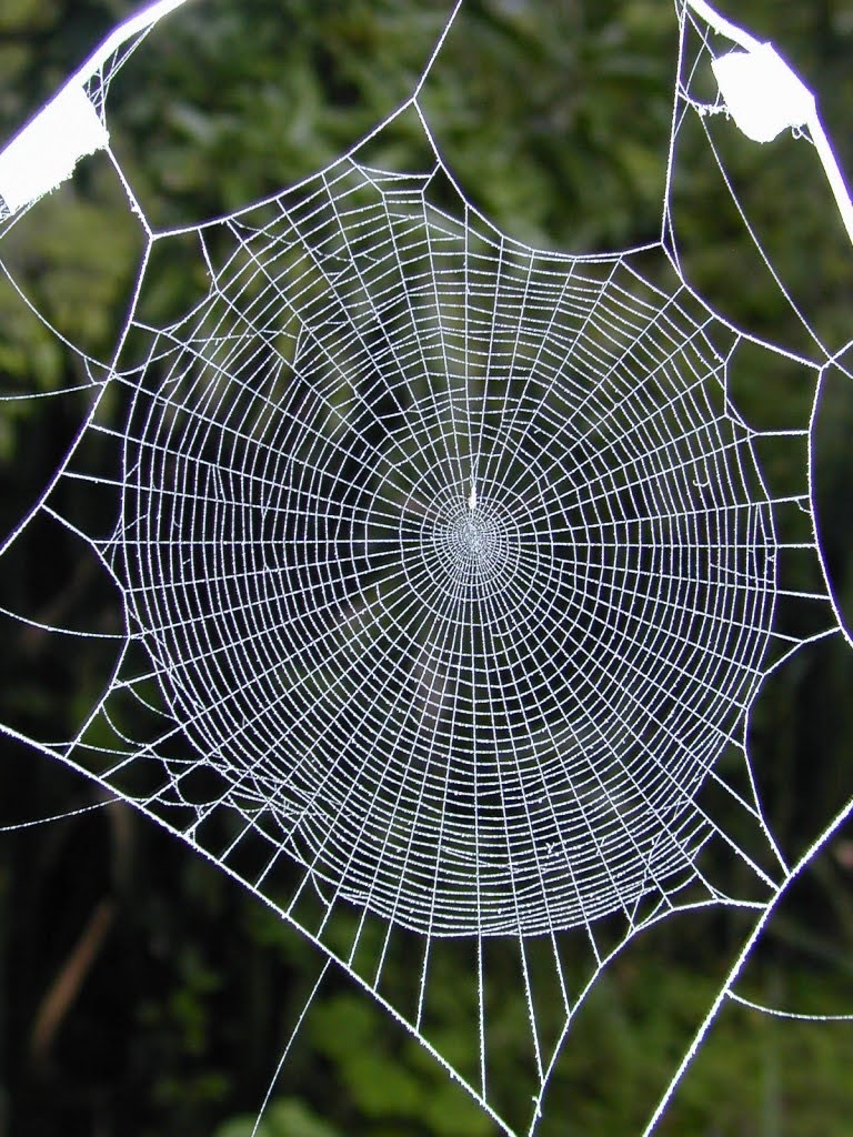
It seems to me that webs consist of several different types of member, which exist within a distinct structural hierarchy. In the first instance there are a series of threads which anchor the web to its surroundings, we shall call these the moorings.

The moorings are connected to the corners of an outer primary frame, which encloses the web. At each corner a secondary frame joins both sides of the outer frame together, but without touching the corner.

A series of radial threads extends from the centre of the web onto the primary and secondary frames. Together these members give the web its overall shape.

A spiral thread winds from the centre of the web towards the outer frames. Unlike those discussed thus far the spiral thread is made of a sticky silk, which is thinner than the other members, and is intended to catch the spider’s prey.

Before we consider how this rather spindly arrangement of threads manages to resist the impact of spider prey, and the force of strong winds, it is worth explaining a key structural principle.

The theory of elasticity dictates that when a load has several different load paths to choose from it will always prefer the one which has the greatest stiffness. In simple terms load is distributed between members according to their stiffness with the stiffest parts attracting the most load.

The importance of this principle may be illustrated by considering what would happen if spider’s designed their webs a little differently. Let us suppose that the hypothetical Institution of Web Safety, were to decree that secondary framing was no longer permitted and therefore radial threads must connect directly to the outer primary framing on all sides. Connecting directly to the primary frame, sounds like a simplification of the structural load-path. That must be good, right?

A further implication of the IWS’s directive would be manifest at the corners of the frame; the radials would now be connected directly to the moorings. Again, that must be a worthwhile safety improvement, because load is directed straight to the point of support.

We can test our theory by imagining a hypothetical fly careering into the web. We want the web to absorb the impact without breaking; that would be bad for the spider’s prospect of lunch.

This means that we want the web to spread the impact force across as many structural members as possible. The more members mobilised to resist the applied load the smaller the load each will carry.

Immediately after the fly strikes the sticky spiral the web’s load-path swings into action. The spiral is connected to lots of radials and begins to share its load. But now something has gone wrong, the load has reached a radial which is connected directly to the moorings. Being connected to the point of support this radial is much stiffer than adjacent radials, which are attached to the outer frame, which has started to flex. Load is immediately attracted out of the radials connected to the outer frame in favour of the stiffer pathway. Soon the radial connected to the mooring is carrying nearly all of the load and is stressed to breaking. Our spider’s lunch is about to escape.

Surprised by the evidence of systemic failure in radial web members the IWS takes the decision to withdraw its directive and reinstates secondary framing, which once again must be connected to the outer frame either side of corners.

Soon an unfortunate fly finds itself bumping into a web with newly reinstated secondary framing. Once again the spiral members spring into action and begin to transfer load into the radials, but this time something different happens. Instead of load being directed straight to the moorings it finds itself being directed into the secondary framing which begins to flex before re-directing load back towards the middle of the outer framing and away from the stiff corners.

The outer framing begins to flex and in doing so starts to engage other radials to which it is connected, before long much of the web is flexing and load sharing is being maximised. On this occasion there is going to be no failure. It looks increasingly like the fly is doomed and the spider will be enjoying lunch.

It seems to me that the web’s structural arrangement is designed to avoid stress concentration. This key feature maximises load spread and minimises the stress in individual members. Another consequence of the redistributive process is that the web becomes less vulnerable to local damage; because load can by-pass those areas.

Thus spider webs have a highly efficient structural form optimised for absorbing impact and for ensuring spiders remain well fed.  

Sunday, September 27, 2020

On Stegosaurus

The original idea for this post was to show an animal’s skeletal structure and explain how it works. I have chosen to do this using a stegosaurus skeleton for two reasons. 

Firstly, this blog is going to be a bit speculative, because I don’t know anything about animals or their skeletons. In the event that a biologist or anatomist finds him or herself reading this blog there is a high probability I shall be politely informed that I don’t know anything. Based on this I figured that my best form of defence would be to choose an animal for which there are no living examples. This way I can argue that since there are no living examples what said animalist thinks they know is mere speculation. No-one can prove otherwise.

Secondly, stegosaurus is a dinosaur and dinosaurs are cool, every kid knows that. Of course I could have chosen T-rex or triceratops, but I think those are the obvious choices and I happen to like stegosaurus so that’s what I’ve chosen.  Here goes….

It seams to me that the spine of an animal, which supports its head and tail are analogous to a thin flexible truss; in fact a special type called a vierendeel truss. To explain this I am going to need to make a few assumptions. Self-evidently all animals walk, run, jump, climb and so forth. Okay, I don’t know whether the last two are true of Stegosaurs, but neither do you. See how effective that defence is? Anyway, movement gets a bit too complex for my stated aim of explaining how skeletal structures work. With that in mind I am going to assume, for the purposes of this blog post, that we have a stationary stegosaurus standing on all four legs.


Based on this the first observation we shall make concerns the legs. The fore-limbs, compared to the hind-limbs, are rarely small, however they are still stocky and have the appearance of being load bearing. The larger hind-limbs and pelvis are larger and would appear designed to carry greater load. This corresponds with the head and neck being rather small when compared to the size and bulk of the hind-quarters and tail.

The stegosaurus’ spine bridges between the two sets of legs and cantilevers beyond them at both ends in order to carry the neck and tail. To understand the structural implications of this arrangement we must first learn something about bending moments.

A bending moment is a turning force whose magnitude is the product of force (or weight) multiplied by the distance (known as the lever arm) to the nearest point of support. The greater the distance to a support; the greater the bending moment.

Consider if you will the following thought experiment. Supposing the stegosaurus’ fore-limbs were located at the end of its nose. I know that’s daft, but run with it. The distance between the nose and its legs is zero therefore no matter how heavy the nose the resulting bending moment is zero.

Now suppose the fore-limbs are located at the back of its head. The bending moment has increased from zero in proportion to the length of its head. I hope you can see where I am going with this. Now suppose the fore-limbs are back where they should be attached to the shoulders. The bending moment has now increased in proportion to the length of a stegosaurus neck and head.

If we were to portray the magnitude of the bending force graphically it would look like a triangle, being zero at the nose and increasing to a maximal point where the legs meet the shoulders. We could repeat the same process starting from the tail. The bending shape would be the same, though the height of the triangle would be bigger because the tail is longer and heavier.

We are now left with the bit in the middle, we need to join the two triangles together. Of course the  body of the stegosaur is somehow attached to the spine (I told you I am not an animalist). We’ll get back to that subject later, but for now we will simply note that the weight of the body must pull down on the spine. It follows that a line depicting the bending moment will join the two triangles, by sagging in middle. It might look a bit like the diagram below. 


The interesting bit; also the bit where I might start to get into trouble; is how the spine resists these bending forces.

The first thing we notice about a stegosaur spine is, like most spines, the odd shape of the vertebrae, which is distinguished by three parts, at least to my eye. There is the oval shaped portion located at the anterior. The lower part is of bone and the upper part has a hole where the spinal cord would be. 

The second feature is the piece of bone that projects vertically from the middle of the vertebra to form the posterior.  This is where the ligaments and muscles of the back are connected to the vertebrae.

The third feature is the two transverse projections; one either side of the vertebrae. These are where muscles and ligaments attach to the spine and are also the points from which the ribs are articulated. The fossil stegosaurus vertebrae pictured below is quite tall and for reasons that will become clear is postulated to be from the lower part of the back.

When the vertebrae are aligned in a row, as they would be to form a spine, they start to resemble a truss with a lower chord of bone and an upper chord of ligament and muscle. You have to imagine the muscle and ligament joining the vertical projections together, as self-evidently they haven’t been fossilised. The internal members of the truss are formed by the bone surrounding the spinal cord and the projection that extends from it. There are of course no diagonal members and that is why the resemblance is to a vierendeel truss.


For this information to be of use we now need to describe how a truss works. We shall begin by considering a beam, which is altogether a simpler and humbler form than the truss. 

If a beam spans between two supports, one at either side, it will deflect in the direction of the bending force to form a curve. As the beam deflects the outer edge of the curve is stretched and is evidently in tension. Conversely the inside edge is squashed and must be in tension. The centre of the beam, known as the neutral axis is neither in compression nor tension; it is at rest.

If we apply the same logic to a truss the outer chord of the truss carries a tensile force and the inner chord carries compression. The internal members of the truss transfer load between the outer and inner chords. 

In the case of our stegosaur based truss the ligaments and muscle at the posterior are ideal for carrying tension and the boney part at the anterior is ideal for resisting compression. This is remarkably good luck, because as nature would have it, the bending moments imparted by the tail and neck of the stegosaur, as shown in our earlier diagram, impart tension on the posterior side and compression on the anterior.

If that is not remarkable enough the depth of the vertebrae increase towards the hind limbs to match the increasing magnitude of the bending forces. Nature has actually fine tuned the size and shape of the vertebrae so that the resulting truss matches the shape of the bending forces to which they are subject.

Having made this observation it is tempting to end this post satisfied that our work is complete, but I am not quite ready to do that. There is one more thing that is just too interesting not to pass comment. I also noted earlier in the post that I would return to this subject.

It is not lost on me that the stegosaur spine has a very distinct curve, which given the apparent fine tuning of the vertebrae, cannot be without reason. Based on that it is, I think, worth a further speculation. 

It strikes me when looking at the bulk of a stegosaur’s body, how is that great big, heavy fleshy part of the animal supported from the spine. Presumably it somehow hangs? I imagine the animal’s flank muscles, perhaps reinforced by the ribcage, are responsible for transferring the load.

It then strikes me that an arch is a rather efficient way of supporting the load and transferring it to the legs. There is of course a potential issue with this load path. Arches generally have large abutments whose purpose is to resist the lateral thrusts generated at the base of an arch and thus prevent it from spreading. It is these same thrusts that make it so difficult to build a house of cards. Of course stegosaurus have no abutments.

There is a potential solution, which is to be found in the form of a bow string arch. Sometimes when there is no opportunity to provide bridge abutments the engineer will instead join the arch supports together with a tie member. This works by causing the two sides of the arch to pull against each other. Since the pull is equal and opposite equilibrium is maintained and the arch is prevented from spreading.

My final speculation is therefore that the stegosaurus’ sternum and chest muscles provide a tie, which form’s a bow string truss made of meat and bone.

Now I can finish the post and wait to be shot down by people that know what they’re talking about. I shall be lying in wait with my pre-prepared speculation defence.

On Ice Shelf Cracking

Tension Cracks in the Brunt Ice Shelf Yesterday the BBC news website published images showing a large section of the Brunt ice shelf in Ant...