Showing posts with label compression. Show all posts

Sunday, August 22, 2021

On Lock-down Tyres

Why my car tyres are flat?


I left the house this morning and found that my car tyres had gone soft and one was completely flat. This was a rather curious state of affairs, because I had not driven anywhere to acquire a puncture, due to the covid-19 lockdown. I live in a quiet village and have good neighbours with whom I am friendly; so it seemed unlikely that anyone would have tampered with them. Nevertheless, I did inspect the tyres to make sure that there had been no foul play. There was no visible damage to the tyres and layers of grime on the valve cap indicated that it had not been loosened recently.


I like a mystery and this got me to start thinking about whether there was an engineering reason why my car tyres had become soft. The first potential culprit was the weather. The differing seasons bring with them settled and unsettled weather, which is of course linked to air pressure. It would be rational for the internal pressure in the tyres to be affected by changes in external air pressure. While this may have been a factor it did not seem to be a good explanation, because though the weather has been inclement recently it has not been unremarkable. Scotland regularly experiences inclement weather, often far worse than it is now. This begged the question that if weather was responsible for my tyres’ loss of pressure why had it not happened before?

The only thing that was really different to normal was that the car had not been used, as there was nowhere to go during lock-down. Cars normally deteriorate due to wear and tear; inactivity would therefore seem like and odd, and somewhat ironic, causation. That got me to thinking about what the mechanism for such an outcome could be. I soon found myself reverting to type thinking about materials and load paths.

The weight of my car is split between four wheels, but not evenly. With an empty boot [trunk for American readers] the car engine is responsible for there being more load on the front axle than the rear. This was consistent with the front tyres being flatter than those at the rear, so perhaps I was on to something.

Weight is transferred from the rotor to the wheel hub by four bolts and then from the hub to the tyre by air pressure. When I was growing up tyres had a pressurised inner tube, but today there would seem to be reliance on the joint between the hub and tyre being sealed tight by pressure.

The hub must be exerting a downward force onto the pressurised air at the base of the tyre, which is resisted by an equal and opposite upward reaction from my driveway via the tyre. The air inside the tyre does not like being squeezed and will try to escape out of the way causing the sides and top of the tyre to experience an outward thrust that would cause it to be stretched. Thus, the bottom of the tyre would be experiencing compression while the top and sides experience tension. 


With inactivity seemingly the critical factor I concluded that my tyres did not like this state of affairs for an extended period. I reasoned that this might be because they are intended to be spinning, such that each part of their circumference takes its turn at bearing compressive and tensile load.

Conversely if my car remained stationary then the load experienced would become quasi-permanent rather than temporal. This opened up several possibilities. Perhaps constant tension resulted in the structure of the rubber becoming elongated in such a way that it was more permeable to air, or perhaps constant compression made the rubber at the base less flexible and therefore more permeable. 

Alternatively, perhaps the seal between the tyre wall and the hub starts to slip with the constant application of load. It would seem reasonable to postulate that such an effect would become more pronounced as pressure is lost from the tyre, because the seal is reliant on their being a positive pressure.

I am not sure if any of these potential explanations are correct or if they all play a role, however irrespective of this I shall in future be making sure that my car wheels turn regularly; even during covid lock-down. 

I shall view my theory as proven if my tyre problem does not return....we shall see.


Sunday, August 15, 2021

On Pentre Ifan

Some observations about Dolmen


This evening I watched a documentary presented by Alice Roberts. I don’t think I have watched a programme presented by Dr Roberts that hasn’t been interesting, and this one was no different, except that the most interesting thing wasn’t strictly the topic. The documentary was about the bluestones of stonehenge, but it strayed ever so slightly to Pentre Ifan in Wales were I was introduced to Dolmens. These are Neolithic structures, which predate Stonehenge. There are lots of them around the world and some are thought to be around 7,000 years old. The Dolmen at Pentre Ifan is a spectacular example, whose massive capstone appears to float above the tips of three standing stones. I expect that’s why I noticed it and why Alice Roberts chose that example.


Archaeologists believe that Dolmens were ancestral tombs, because scattered human remains are often found between the standing stones. Some also believe that they were originally buried beneath a mound of earth or smaller stones.

Interesting as these conjectures are I can’t get past the graceful form of the structure. I suspect that archaeologists, for the most part, take for granted that the monument stands, while going to great lengths to try and understand how it got there and how it was built. I think I understand why this is, but there is a certain irony that for such an old object so much more effort is expended on the temporal than the permanent [1].

To me the fact that Pentre Ifan is standing at all is more interesting and is the subject of this post. Maybe on another occasion I’ll fall in to line with everyone else and have a go at speculating how such structures are built, but not today.

I should of course pause to note that I have never seen a Dolmen in person, nor do I really know anything about them, other than tonight’s brief introduction. I am keen to remedy that and will aim to visit some examples when the covid-19 lock-down has ended, however that isn’t going to stop me from donning my engineering hat and doing some speculation of my own. I shall be doing so based on a few images I have pulled off the internet; what could possibly go wrong?

I am going to start with the assumption that the stones are igneous rocks, because they have that appearance and because there are outcrops in the the relevant part of Wales. This ought to make the rock relatively strong; though like any rock it will be brittle and weak in tension.

There is evidence of horizontal fractures in the capping stone and equivalent vertical features in the standing stones. Structurally this is not a terribly efficient arrangement. A stronger arrangement would be to align planes of weakness in the standing stones horizontally so that they are squashed together. For the capping stone it would have been better to align them vertically so as to avoid separation due to shear flow generated by bending forces.

I suspect that this was not done, because creating the great slabs of stone required cleaving them from the parent rock by exploiting the noted weaknesses. Without them stone-age workmen would have had difficulty creating such slabs with primitive tools.

The next thing I notice is that the capping stone appears to be fatter at one end than the other and that the soffit appears to have been cleaved as it progresses towards the thin end. I suspect that it was not originally so.

The fat end is supported by two standing stones, while the thin end is carried by one. In the short axis the fat end of the capping stone can bridge laterally between two close supports. It can possibly do this in direct shear and without inducing bending.

Conversely, in the longitudinal direction the capping stone must span almost 5 meters between the single and double support. This almost certainly results in it experiencing bending. As has been seen in prior posts bending causes the top surface of a beam to experience compression and the soffit to experience tension. 

In order for this to happen a beam will also experience a laminar shear flow in the horizontal direction. This can be understood by imagining a beam divided into horizontal slices. For tension to be experienced on the soffit while compression is experienced on top it is necessary for the imaginary slices to slip past each other.

The consequence of these actions appears to be evident in the structure. Since stone does not deal well with tension it is inevitable that small cracks must have developed in the soffit. There would also have been lateral movement along the rock’s natural horizontal weaknesses. It is conceivable that together these effects led to the soffit spalling, however it is more likely that they were abetted by other effects too.


Rainwater will have soaked through the top surface of the slab and migrated under gravity to the soffit. While moisture would evaporate quickly from the top the soffit would remain in the shade helping to keep the stone damp and wet. Persistent dampness will have weakened the rock structure and freeze thaw action would have exploited the many small cracks and natural weaknesses. Eventually the fractured rock would spall until it arrived at a horizontal plane of weakness whereupon the process would start again.

Perhaps another aggravating factor would be expansion and contraction due to the cycle of heating and cooling. Since only the top surface is exposed to the sun there is likely to be a thermal gradient in the capping stone as it warms. During the day the top of the stone would expand relative to the soffit and thereby start to close some of the soffit cracks. Conversely, during the night it would start to contract and thereby re-open the soffit cracks. Thus, by repetition the soffit would slowly be fatigued and further cracks induced.

When considering thermal effects it is worth noting that having only three small points of contact between the capping and standing stones is probably beneficial, because the soffit is free to articulate. More severe cracking would be much more likely if the top surface were free to expand and contract while the soffit was held in place by more restrictive contact. 

It would therefore seem that there is a good explanation as to why the capping stone is fatter at one end than the other, and all else being equal, by what mechanism it will eventually fail.


The standing stones appear to carry the capping stone effortlessly. The fact that they do so with such small points of contact would suggest the compressive strength of the stone must be relatively high. That said, it is assumed that the contact surfaces could not have been prepared to a modern standard and therefore the distribution of load will not be entirely even. This will have allowed load concentrations to be formed which may over time pry and fracture the rock locally.

This is important because compression in the standing stones will cause lateral bursting forces to develop due to passion’s ratio [this is another concept we have seen before]. Within the body of the stone compressive stress is generally low and therefore the bursting forces have little effect, however where load is concentrated stresses are higher. If such stresses coincide with a vertical plane of weakness it could encourage the bursting forces to form a split in the rock. As with the capping stones this could be exacerbated, either by moisture penetration, or by bending induced by one side of the rock being warmed faster than the other. There does seem to be some evidence of such processes at work on the surface of the standing stones.

Another facet of the pictured Dolmen is how it maintains lateral stability. It is self evident that there is no rotational resistance at the junctions between the capping stone and its supports, therefore we must conclude that the standing stones must cantilever from ground level. Since the capping stone bears heavily upon them there will be sufficient friction generated to share lateral load between the standing stones according to their stiffness.

Lateral loads would come from the wind and to a lesser extent thermal effects. There also appears to be a slight incline to the capping stone, which would imply there is a resultant lateral load, due to the stone’s self-weight, to be resisted.

Something else that is structurally relevant, though I am unsure whether it was intended, is the orientation of the standing stones. The two stones at one end are orientated perpendicular to the single stone at the other. Strength being proportional to the cube of depth this arrangement presents the full depth of at least one stone in each orthogonal direction, thus maximising cantilever action in both.

It is also interesting that the end supported by two stones is aligned with the noted incline to the caping stone, thus maximising resistance to the permanent lateral load. The possibility that this was intended is intriguing.

A different explanation would be that since one end of the structure has two supports, and the other just one, there could have been differential settlement. Assuming this were the case the narrow supports would again have been beneficial, because they would have allowed the capping stone to rotate and find a new point of equilibrium. Alternatively, more substantial supports would have likely led to fracture. I have no idea what the bearing strata beneath the standing stones is like, but in the absence of further evidence the mechanism for differential settlement seems plausible.

Of course it is also possible that the fractured soffit could have contributed to creating the observed incline too.

While the depth of embedment of the standing stones is not clear from viewing the surface it seems reasonable to assume that it must be substantial to ensure there is sufficient passive resistance to prevent overturning or sliding of the stones. In a uniform soil it would also be reasonable to assume that bearing pressure would increase with depth.

On paper it is perhaps possible that the stones could be mounted near the ground surface with stability being maintained by their shear size and mass. In the real world this does not seem plausible as the surface of the ground is prone to become waterlogged, there is also the possibility of frost action. Either of these effects could be sufficient to topple the stones.

Two further practical matters exist. Firstly, a shallow footing would be vulnerable to digging near the base when bones were to be buried. 

Secondly, and perhaps more importantly, the processes of standing large stones on end without a crane, or other modern equipment, would seem to make it necessary to tip them into a hole. If said hole were then packed tight with backfill it would lock the stones in place allowing them to behave as cantilevers.

Here I run the risk of getting into the question of how the stones were erected and I said I wasn’t going to do that. I best stop here.


[1] I base this thought on working with a few archaeologists and the number of documentaries there are about erecting Stonehenge, rather than any proper search of the archaeological literature.


Sunday, August 8, 2021

On Pendentives

A tale of two domes

Perhaps two of the most important domes from antiquity are those belonging to the Pantheon in Rome and the Hagia Sofia of Istanbul. Although the latter is to be found in modern day Turkey, it is of course from the era of Byzantine rule in Constantinople and is therefore of Roman origin.


From their outward appearance the two domes would appear to be similar, indeed how different can the construction of a dome be? Further inquiry would reveal that the materials used to construct the two domes are different. The Pantheon is made of unreinforced concrete, while the Hagia Sofia’s dome is of masonry. Indeed the Pantheon remains the world’s largest unreinforced concrete dome to this day.


This difference is interesting, but in my view is not fundamental to the way in which these two revolutionary structures work. I am perfectly aware of the Pantheon’s oculus, its coffered soffit, the variation in concrete mix over its height, all of which were designed to save weight. These are important details, which are both interesting and worthy of study, maybe I will write about them in some future point, however they are not directly relevant to the subject of this post.

The first thing to note is that classical domes, like later gothic structures, are what I would describe as gravitational or compressive equilibrium structures. That is to say that their structural adequacy is dependent on their shape and not on materials science. This is possible because actual stresses are compressive and sufficiently low that, providing equilibrium is maintained, material strength is unimportant. This makes sense because materials science, at least in the modern sense of stresses and strains, did not exist when they were built. 

Those familiar with the structures in question will no doubt be aware of known cracking in both domes, which might be taken to suggest that there is in fact some material science going on, however as we shall see this is not the case.

To understand the primary difference between the Pantheon and Hagia Sofia, perhaps it is first necessary to explain how a generic dome works. In section domes behave in a similar manner to arches, because their curved profile exerts both vertical and lateral thrust at the seating[1]. Domes are of course unlike arches in the sense that they are 3D structures. This means that the aforementioned vertical thrusts are expressed as compressive meridional stresses extending from the crown of the dome to it’s base. The lateral thrusts push outwards in all directions generating a circumferential or hoop stress that cause domes to spread. It is the way in which the meridional and circumferential stresses are resisted that makes the difference.

Like barrel vaulted structures from the classical period of history the Pantheon is supported on heavy walls that follow the profile of the roof structure, in this case a cylinder, in order to buttress the roof against spreading. Some descriptions I have read speculate a stepped thickening observed at the dome’s base is designed to provide a circumferential tie. Maybe their authors have done more research than me and have data to support this view, however I am disinclined to adopt it based solely on my own intuition that the tensile capacity of concrete, albeit Roman concrete, is too low. Also, if tension were present it would imply materials science is at work to provide the required equilibrium, which is philosophically less satisfying.

It occurs to me that a more elegant solution, which maintains the idea of gravitational equilibrium, would be one where the purpose of the steps was to increase weight at the head of the supporting wall in order to push the dome’s thrust line back into the supporting walls. In essence it would behave, at least in my estimation, like the pinnacle atop a flying buttress.


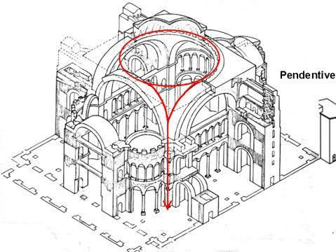
The dome of the Hagia Sofia is different. It does not find support from heavy buttress walls. Rather it straddles the four corners of a vast open space into which light and air may flood. In character it is a medieval structure whose load paths concentrate the dome’s weight into a carefully defined masonry skeleton. The invention that makes this possible are the inverted triangular masonry panels, known as pendentives, that are located over the four supporting piers. As they spread outwards from their apex a series of four arches are formed on the dome’s perimeter. Together these elements funnel load into the supporting piers where the in plane arch thrusts are buttressed.

It is evident however that there remains unbalanced thrusts perpendicular to the apex of each pendentive arch. Equilibrium is restored by hemispherical domes that lean in the opposite direction to the dome’s thrust in one direction and buttresses in the other.


And so it is that the dome at Hagia Sofia represents a transition between heavy buttress walls and gothic cathedrals of the later medieval period, whose structures had a more clearly defined order of primary and secondary elements and a more sophisticated understanding of load paths.

Now, to the aforementioned cracks in both domes. Many seasoned observers hold the view that these are the result of past seismic events and differential settlements. Indeed the original dome at Hagia Sofia is known to have collapsed during an earthquake leading to the present cupola being constructed with a higher profile in order to reduce the magnitude of lateral thrusts. 

Nevertheless it would appear that in spite of movement to both structures gravitational equilibrium has been restored. They remain stable, or at the very least, are moving very slowly.


[1] For further information I have written several prior posts relating to the behaviour arch structures.

Sunday, July 18, 2021

On Grass & Buckling

Why you shouldn’t walk on a frosty lawn

An interesting thought that hadn’t struck me before is why it is possible to play sport on grass without it being ruined. I am not suggesting that sports pitches don’t suffer from wear and tear; self evidently they do. After two weeks of tennis in the summer the courts at Wimbledon are not in the same condition they were at the start of the tournament. Similarly, after a season of football or rugby pitches around the country need time to recover, albeit pitches today fair better than they did in the past, but that’s not really what I mean. How is it that sport can be played on grass at all? 

It takes no effort at all to pluck a blade of grass and almost none to tear or cut it, how then can we walk on grass without damaging it let alone run and jump? I think the answer is to be found in a structural principle known as Euler[1] or Strut buckling. Euler buckling is a special form of compression failure, which applies to slender structures and is named after Leonhard Euler who sorted out the mathematics. Slender structures are those, which are thin relative to their height.

When a squat structure is subjected to compression it will fracture and split if it is made of a brittle material. Alternatively, if it is made from a ductile material it will bulge and deform, however a slender structure will buckle before any of these states are reached.

Buckling is essentially the point at which a structure subjected to compression gives way due to a rapid increase in lateral deflection. The reason deflection increases rapidly is because the onset of buckling instigates a feedback loop.

When buckling begins the structure is displaced laterally, which causes the compressive load it carries to be applied eccentric to the line of support. As we have learned in earlier posts an eccentric force generates a bending moment, which causes increased lateral displacement. Thus the feedback loop is set in motion.


Euler’s work teaches us that the load at which buckling commences is directly proportional to the stiffness of the structure and inversely proportional to the square of its length. This tells us two important things:

Firstly, doubling the stiffness of a structure will double the buckling load, whereas doubling its length will reduce the buckling load by three quarters. The length of the structure is therefore the most significant factor.

Secondly, providing the material is ductile and will therefore remain elastic, its strength plays no role in Euler buckling. This means that once the compressive load has been removed it will recover and return to its original shape. For those who are interested elasticity is covered in a prior post, On Ductility.

These are the properties which make walking on grass possible. A blade of grass has a low material stiffness and is tall relative to its thickness i.e. it is slender. For this reason when you step on grass the blades simply buckle elastically and then recover when the foot is lifted. It is also worth noting that grass grows from the root rather than the tip so any damage that does occur can be repaired from below the damaged part.

It is often said that you should not walk on a frosty lawn. In light of our buckling logic the reason for this becomes clear. Grass, being a plant, is made or cells which contain water. I am sure biologists would put it better than this, but I think that’s pretty much the case. When a frost sets in water contained in the cells will freeze and make the normally flexible blades of grass brittle. It follows that if you were to step on a lawn in this condition the frozen blades would no longer be elastic and instead of buckling they will fracture. Thus permanent damage is done.


So that’s my answer; sport can be played on grass, because each blade is a small slender structure that behaves according to the rules of Euler Buckling. I suspect that the normal wear and tear that we see on sports pitches is primarily due the lateral movement of feet, which would presumably apply horizontal shears that tear and rip at the buckled blades. That said, this cannot be the dominant behaviour or pitches would become rather more damaged than they actually are.


[1] Pronounced Oiler

Sunday, July 11, 2021

On San Petronio

Gravitational equilibrium & the square cube law


‘Gulliver’s Travels’ is a classic of English Literature written by Jonathan Swift in 1726. It is intended to be a satire of human nature and ‘travellers’ tales’. In the book its protagonist visits the fictional countries of Lilliput and Brobdingnag. The citizens of the former are 12 times smaller than Gulliver and in the latter they are 12 times bigger.

Of course every reader of the book knows that Lilliput and Bribdingnag are fictional, but perhaps fewer might realise that they are necessarily fiction in any possible world that follows the same physical laws as our own. The reason for this is described by the square cube law, which was first attributed to Galileo.

According to this law the size of things cannot be indefinitely scaled up, because the physical properties of objects change as they increase in size. Consider a cube with sides one unit long. If we were to double the length of each side then the surface area of each face will increase from 1 to 4 units. The volume of the cube, and by extension the quantity of stuff from which it is made, increases from 1 to 8 units i.e. doubling the linear dimensions causes the surface area to be squared and the volume of stuff to be cubed.

In other words the rate at which the volume and weight of an object increase with size is greater than the rate at which its linear dimensions and surface area increase.


Conversely, the strength of things, normally expressed as a limiting stress, is independent of size
[1]. It follows that as things become larger, while retaining their original proportions, they will eventually reach a point where they can no longer support their own weight. This places an upper limit on how big things, including people, can get.

This is a vexing problem for modern day architectural students, who are surprised to learn that the model they have spent hours building does not prove that the structural gymnastics their design requires are viable in the real world.

There is of course an exception to the square cube law, though not a true exception. The square cube law does not cease to work, rather it is not discernible within the normal range of scaling for certain objects.

An example of such an object from the natural world would be a mountain. An equivalent structure form the man-made world would be a pyramid. Both structures come from a class of things that share three key ingredients. Firstly, they are both made of stone, which is a natural material with a very high compressive strength and low tensile strength. Secondly, they are both compression structures that assiduously avoid tension. Thirdly, they are stocky and solid structures. Not solid in the sense that they are strong, though that is indeed true, but solid in the sense that they are not hollow. The implication of being stocky and solid is that they are not prone to buckle, as a slender or thin walled structure is. A second implication of stockiness is a large cross-section, which implies low stress.

These then are the ingredients for subverting Galileo’s square cube law and within the class of things which have these ingredients there is a group of structures that does so with a style and panache that is difficult to surpass. They laugh in the face of the square cube law.

I am of course talking about gothic structures; those great stone cathedrals of the late medieval period with their quadripartite vaults and flying buttresses. I am often asked, mainly by my dad, how it was that medieval masons created such structures in the absence of modern structural theory. The stock answer is that they used rules of thumb, but for me there has to be more to it than that.

How on earth did they manage to design structures, using rules of thumb, that modern analysis shows us to have near perfect proportions. Rules of thumb are intended to apply generally, but must necessarily be derived from the particular. The further a design departs from the particular the less useful a rule of thumb is. 

Gothic structures do have similarities, but there is also great variety in their design, which ought to make rules of thumb less helpful.

Perhaps the answer to this dilemma is to be found in a process of trial and error. While there was undoubtedly a role for trial and error I am not convinced that it played a central role, at least not in the commonly understood sense. I hold this view for several reasons:

Firstly, most cathedrals took hundreds of years to build and though master masons may have worked on several, they would not, in their own lifespan, have time to learn all the necessary forms by trial and error. This brings us back to rules of thumb. Secondly, while there is evidence of design evolution over time there is relatively little evidence of major failures, which is odd given the innovative, and often spectacular, designs adopted. Furthermore, when known failures occurred they were often, though not always, associated with abnormal events like earthquakes or phenomena external to the structure like differential settlement.

We therefore have much evidence of trying daring new things, but scant recorded evidence of failure [2]. This is not entirely a surprise, because cathedrals are expensive and their proprietors were not stupid. Master masons would not have been in charge for long if their structures kept collapsing.

To find a satisfactory explanation I think we need to return to the square cube law. If a structure could be designed to subvert the square cube law then a successful pattern would be successful at any scale. It follows that if you could demonstrate a particular form of structure would stand using a small model made of wood then it would also stand if it was scaled up to full size. 

I do not know whether masons understood that they were subverting the square cube law. I suspect that they didn’t, but I do think that they understood perfectly well the load-paths and principles that were necessary to keep a stone structure in equilibrium. I think they fully understood that tension was the enemy and that gravity must be harnessed to maintain compression in all parts of the structure. 

They were specifically designing structures to achieve gravitational equilibrium and they were doing it by experimentation with scale models. They then used rules of thumb, derived from these models, to scale up their findings to full size structures.


Happily for the masons this methodology was just perfect for avoiding the square cube law, whether they knew it or not, and in this way spectacular and innovative designs could be realised without needing to know anything about materials science, stresses or strains.

While this theory involves a heavy dose of speculation it is not without evidential support. For example, we know that Antonio Vicenzo the designer of San Petronio church in Bologna commissioned a model of brick and plaster at circa one eighth scale. It was around 19m long and 6m high. I expect that it was used to convey the design to its proprietors, but I don’t think it is too great a leap to posit that it might also have played a role in the church’s structural design.


[1] I accept that all bets are off at the atomic scale, but we don’t normally consider atomic forces when designing building structures, bridges and the like.

[2] I know that absence of evidence is not evidence of absence, nevertheless evidence is sometimes notable by its absence, particularly when there might be a reasonable expectation to find some.


Sunday, June 27, 2021

On Lunes & Cracks

Conserving St Peter’s Basilica


The dome of St Peter’s Basilica in Rome is one of the most recognised structures in the world. It was completed around 1590 and was conceived by the genius Michelangelo. There are many reasons why it is special structure, but perhaps the most important is amongst the least well known.

By around 1680 cracks were being reported in the dome, which unsurprisingly caused some to question its safety. Concerns were exacerbated following an earthquake in 1730. Meridional cracking, associated with a dome’s tendency to spread at the base, was well known in the sixteenth century and therefore, following a detailed investigation, a recommendation was made to supplement the existing wrought iron hoops, which were intended to prevent spreading, with three or four more.


It would seem that the Vatican had travelled a distance since Galileo’s heresy trial and the incumbent Pope Benedict XIV, unlike many designers and practitioners of the day, was impressed by the progress made by scientists and mathematicians of the day. He therefore commissioned three of them; Thomas Seur, Francois Jacquier & Roggiero Boscovich to examine the subject. The publication of their findings in 1743 was a seminal moment for Structural Engineering, because they had based their conclusions on a mathematical analysis of the dome. It was the first known occasion when this was done in any meaningful way. Their approach included a model of the dome’s weight, its materials and two different behavioural scenario’s. The method they adopted for combining this information would today be called ‘virtual work’.

They concluded that the existing iron rings embedded within the dome were insufficient to prevent spreading and that the dome would collapse. They therefore proceeded to calculate the number and proportions of additional rings. This was of course a safe recommendation, however it overlooked the rather important fact that the dome had not in fact collapsed and was very much still standing.

Though they were three of the smartest mathematicians of their day they had made the same basic error that almost every graduate engineer makes at some point. They had placed their confidence in their model over what they could see with their eyes. One of the most important truisms of structural engineering is that a structure will remain in place until it has exhausted every possible means of standing. Consequently, if a mathematical model says a structure will collapse, but it stubbornly refuses to do so, then one is obliged to conclude that the model is wrong and not reality.

The presiding committee responsible for the church’s upkeep did what committees often do. They ignored the expert report and continued to monitor the structure. Benedict was also dissatisfied, but wished to persevere with a scientific approach. He commissioned a new study by a different expert Giovanni Poleni. 

Poleni criticised aspects of the first report and tackled the problem with a different approach. While he conceived his own mathematical model, Poleni was also aware of Robert Hooke’s work on the stability of arches, which is described in an earlier post [On Balloons, Chains and Arches]. He therefore imagined the dome to be split into a series of lunes each of which rested against an opposing lune on the other side of the dome. He then used a physical model to demonstrate that the line of thrust for a pair of lunes lay within the depth of their cross section and would therefore meet Hooke’s criteria for a stable arch. By this reasoning the whole dome, being a series of balanced lunes, would be stable in spite of its meridional cracks.

Nevertheless, Poleni also recommended four additional wrought iron hoops, which were installed in 1744. A further hoop was added in 1747, when it was discovered that one of the originals had in fact fractured.

While the application of mathematics to structural engineering problems, which was pioneered by Seur, Jacquier and Roggiero, would prove successful in the long run it is not difficult to see why it was unsuccessful to begin with. 

While mathematicians and scientists had been publishing treatise on engineering subjects from the early eighteenth century, architects and engineers of the day were unacquainted with mathematical argument and treatise were therefore largely ignored.

A second, and perhaps more significant issue, was the relative maturity of the respective disciplines. Eighteenth century mathematical models, though brilliant in their conception, were no match for 1,000 years of engineering experience, which had refined and optimised known structural forms about as much as it was possible. The only conceivable  advantage for science would be for the conception of structures for which there was no precedent.

This dichotomy caused a divergence in engineering practise between Britain and its European neighbours. While France and Germany forged ahead with academic schools of engineering Britain largely adopted an empirical approach. Unsurprisingly the continental Europeans produced more impressive academic works, however Britain prospered with its empirical approach, which produced closer alignment with the real world and therefore greater efficiency.

Britain’s engineers did not dismiss theoretical works, because they were less intelligent or less capable. They simply knew that the best academic theories of the day could not get close to matching the empirical approach they were pioneering.

There is a lesson in this for the modern engineer. Modern codes of practise are becoming increasingly academic and less practical. It is not clear to this engineer that the additional effort required to use them yields a justifiable benefit. I am also quite certain that as in the eighteenth century some modern methods are less efficient than the empirical methods they have replaced.

In some circles our profession needs to rediscover the once obvious truth that a theory, which does not match past empirical experience, is not a good theory.....particularly when it is more complex to use than its predecessor.


Sunday, June 20, 2021

On Pyramids & Ziggurats

Smarter engineering than you might think


It is self evident that ancient structures were not conceived using modern codes of practice and that their designs were based on rules of thumb evolved from a process of trial and error, however there is perhaps some misunderstanding as to what this means in practise. 

It was not, as you might suppose, a process of edging successive designs slowly towards failure with fingers crossed; hoping to stop before you get there.

A rule of thumb, by its mere existence, presupposes the existence of mathematical relationships between objects. How else might proportions and limits be implemented. Furthermore, evidence suggests that trial and error was purposeful and based on underlying principles of logic. As we shall see ancient structures are more sophisticated than you might think.

Ziggurats were built in Mesopotamia on the great plain that lies between the Tigris and Euphrates rivers in what is today part of Iraq. These two great rivers carry vast amounts of silt, often depositing it along the way in times of flood. This created thick deposits of alluvial soil, which are ideal for agriculture, but much less so for constructing large, heavy buildings.

This was not the only geological issue to be overcome. With the Mesopotamian plain being covered to depth with alluvial soil, there is little building stone from which to construct monumental structures.

For this reason Ziggurats were constructed of bricks, made of locally available mud baked in the sun. Sadly, without a protective stone skin, most surviving examples are heavily eroded. That said, on account of their exposed condition, those which remain provide us with clues about how they were constructed.


It would have quickly become apparent to the Mesopotamians that soft alluvial soils would undergo significant settlement when subjected to the weight of a ziggurat and their steep sided construction would have a tendency to spread at the base. 

Successive layers of construction would suggest that they paused and restarted the works on many occasions until the settlements and spreading eventually ceased. In this way the lower layers became layers of fill below a wide plinth or temenos, on which a great temple could be constructed.

This process is not unlike the modern technique of preloading soft ground with great berms of earth. The same technique has been used to improve sites adjacent to the River Clyde in Glasgow.

The Mesopotamians were not, however, satisfied with the pace of construction that this method afforded and they soon conceived another ingenious plan, which engineers today might consider modern.

After every eight or nine courses of brickwork they began to add a thin layer of sand containing matts of woven reeds and cables made of plant tissue. Together these innovations allowed the Mesopotamians to create a primitive form of reinforced earth not unlike that which is achieved today using geosynthetic grids and textiles.

The great weight of construction generates friction between the mud bricks and the reinforcement; clamping them together so that they cannot move relative to each other. This allows the tensile capacity of the reinforcing matts and cables, which is not possessed by the brickwork itself, to be mobilised such that the steep walls of the ziggurat are prevented from spreading laterally. If this were not clever enough the layers of sand in which the reinforcement was laid had two ingenious roles. Firstly, it would have helped to bed the bricks evenly onto the reed matts helping to ensure an even distribution of load and to prevent sharp or uneven edges from causing unwanted damage. Secondly, the sand would suck moisture from the mud-bricks and provide a route for it to escape. This leads to consolidation, increased density and greater strength.

The evidence is clear; Mesopotamian ziggurat builders were not simply stacking bricks until failure was reached. These innovations demonstrate a knowledge of complex engineering principles. 

The Pyramid’s of Egypt are built between the Libyan dessert and the western bank of the river Nile, as it flows towards its Mediterranean delta. On the face of it they appear to have much in common with Ziggurats. They are both large, heavy structures, with steep sides, constructed from masonry. They both impose massive loads at their base and are subject to lateral spreading forces.

This, however, is where the similarities end, because the great pyramid designer Imhotep came up with some rather different solutions. Perhaps the most obvious difference is that Imhotep, and those who followed him, adopted locally available limestone en lieu of mud bricks. It is a much stronger material, which requires a different treatment.

Perhaps the first thing to note is that a pyramid’s weight is not evenly distributed. The maximum pressure is exerted below its centre, reducing towards the edges. This means that a pyramid’s core and perimeter will settle differentially. 

We know that Imhotep understood this because he devised a clever method of preventing the rigid stone blocks from being fractured by said settlement. 

Pyramids are not solid structures. Examples investigated at Saqqarah, Meidum and Dahshur consist of a solid stone core laid at a steep angle, which is surrounded by independent concentric squares of masonry. The inner portion of each square, roughly 4/5, is of roughly cut stone laid in mortar while the final 1/5 is of dressed stone with smooth contact surfaces. The central core also has an outer facing of dressed zone.

Each independent square can slip relative to its neighbour, thus accommodating differential settlement. The efficacy of this process is enhanced by the smooth surface of the facing stones. 

Nevertheless, cutting and dressing smooth stone surfaces is difficult, time-consuming, expensive work, particularly using bronze age tools. It therefore made sense to minimise this type of work by using rough cut stone as the backing, although this does have consequences. While the dressed facing stones have good contact surfaces that distribute load evenly and provide a solid stable base, the rough cut stones have poor contact surfaces resulting in greater potential for consolidation and outward movement.


Imhotep would have known that the inclination of the dressed facing masonry had to be optimised so that it leans into the rough stone and contains its tendency to spread. It has been found that the angle adopted corresponds to the prime numbers 2, 7 & 11. 

These observations demonstrate that Imhotep, and those who followed, had a clear understanding of structural load paths and of building materials. Furthermore, what evidence we have for design by trial and error falls within this rational framework.

The Stepped Pyramid at Medium and the ‘Bent’ Pyramid at Dahshur are good examples.

The former has a strange shape, which archaeologist originally presumed to be the result of stolen facing stones. It is not clear why one would steal from the top and not the base;  engineering appears to provide a better explanation. While the construction follows Imhotep’s settlement mitigation strategy some of the stone has been found to be of poor quality. It’s friable nature caused a local collapse by creating the conditions for a slip plane to develop thus causing the loss of several structural layers due to spreading. 


Similarly, the so called bent pyramid clearly shows that the designer realised part way through the build that the angle of inclination was too steep and had to be reduced to maintain equilibrium and thereby prevent spreading. This demonstrates that he understood something was going wrong and then knew what to do about it.


It follows that for both the ziggurat’s of Mesopotamia and the pyramid’s of Egypt there is clear evidence of structural principles being understood and refined by purposeful trial and error and captured in rules of thumb with a basis in Maths. 

One might argue that they are good examples of qualitative design. They are certainly a reminder for modern engineers that complex sums are secondary to clear thinking about underlying load-paths and a practical knowledge of material.

Sunday, June 13, 2021

On Ice Arches

Understanding ice flows in the Nares Strait

Today an article on the BBC website caught my interest, but perhaps not for reason the author intended. The article describe the premature disintegration of an ice arch that bridges between Greenland and Ellesmere Island. The arch had blocked the so called Nares Strait, much like the damming of a river, thus preventing the southern migration of the ice flow. Viewed from space the arch is spectacular. The images below show before and after disintegration.


The point of the BBC article was to highlight the effect of a changing climate and what might result from increased ice flow. I have no interest in discussing this; it doesn’t remotely fall within my expertise and I don’t have anything new or novel to bring to the topic. 

Instead, what initially crossed my mind was whether this, and similar structures, I assume other examples must exist, might be the largest arches on the planet. I have no idea whether this is the case or not, but one has to think that they must be contenders.

My mind then turned to the question of why such arches form and whether they were in fact true arches at all. As it turns out I think the two questions could be linked. Not that I really know anything about this subject either, but I do at least feel more comfortable to speculate on the basis of structural principals.

The ‘before’ photo shows the ice flow firmly interlocked with the coast of each land mass. The interlocking extends over a distance, which exceeds the width of the strait and that seems significant to me. The reason I view this as important is that a member whose depth exceeds half its width fits the definition of a deep beam. A deep beam is one that is of sufficient depth that its behaviour is no longer governed by bending effects. I therefore wondered whether what we actually had was a deep beam rather than an arch. That gave me cause to think about how a deep beam actually works. It was this that lead me to postulate how, and I suppose why, an ice arch might form.

The effective depth of a deep beam is roughly equal to its span. It follows that there is little load resisting contribution from the ice flow beyond that point. Normally within a deep beam’s effective depth the stresses behave a bit like an imaginary tied arch with a compression zone at the top, which pushes outwards towards the sides. There must also be a corresponding tension zone at the bottom of the beam, the tie, which prevents the internal ‘arch’ from spreading and tension cracks from forming.

The trouble is that this isn’t what we see in the satellite image. The tension zone is completely missing, leaving the observed arch profile at the base of the ice flow. The obvious reason for this would be that ice is an anisotropic material; it is strong in compression, but has little or no strength on tension. Self-evidently, since there is is an absence of tension capacity, the section of ice exposed to tension has, presumably, cracked and floated away prior to the picture being taken, thus leaving behind an arch profile.

That said, while this may explain the formation of an arch profile it can’t be the whole story. If there is no tie stopping the ice arch from spreading why hasn’t the arch itself collapsed? The answer must be that the land mass on either side of the ice flow provide strong buttresses, which contain and resist the outward thrusts. 

This, however, still doesn’t entirely explain what is going on, because if the buttresses are secure then no tension can be present in the ice flow and if that is so why did the bottom of the ice flow fall out.

Assuming the buttress theory to be correct I can think of several potential mechanisms, but I am not sure which, if any, are contributory.

My first thought would be that perhaps the ice formation takes time to interlock with the land mass and the arch is able to spread while it is still forming. Perhaps during the formation process ice at the land interface cracks and breaks, as the ice flow moves south only becoming solid and immovable as it is slowly pushed and squashed into all the available gaps. Perhaps there is also undulation in the ground and some of the ice rides up over the shallow flat parts until it is is resisted by projections.

Maybe, despite the appearance of static resistance, even the arch is moving slowly southwards and the buttresses gradually shift and adjust. Not enough for the arch to fail, but enough for tension cracks to form at the base of the ice flow.

These would seem, at least to me, plausible explanations for the formation of an arched profile. The question is whether what we are actually seeing is in fact a true arch. We had been considering the possibility of deep beam behaviour, but have, without noticing, slipped back into describing the structure as an arch.

I think it would be just as correct to view the structure as a buttressed deep beam with the effect of rigid coastlines replacing the beam’s tension zone. Though this is perhaps an unusual description I happen to think it is a better description than a true arch. I have three reasons for this.

Firstly, I don’t think the ‘arch profile’ forms without the ice flow first trying to behave as a deep beam. Secondly, due to the re-distribution of forces within the depth of the structure, caused by the buttresses adjusting I don’t think you can avoid the conclusion that stresses are set up across the full width and effective depth of the ice flow. Thirdly, using classical arch theory, which has been discussed in prior posts about masonry arches, I don’t think you could stop the thrust line leaking out of the optimal arch shape due to the depth of the structure and the behaviour of the abutments...actually I’m not sure that’s not just another way of stating reason two.

So, that would be my answer. I think that the base of the ice flow has the appearance of an arch, but is in fact a buttressed deep beam, or maybe that’s just a speculative folly on my part. 

One notable point is that I have offered no comment on the ‘after’ picture. I guess that’s because I wanted to talk about the apparent arch itself, it seems obvious that it would start to fail if the ice melts. Maybe the ‘after’ scenario shows what the ice flow looks like as the structure is forming and the ice is being squashed together. I have no idea if that is true, but aesthetically I am drawn to the idea of a circular process. Perhaps if the temperature is lower at higher latitudes a new wider ‘arch’ will form further north.


Sunday, June 6, 2021

On Devorgilla Bridge

Some Characteristics of Stone Bridges 

Last summer I took a camping trip with friends and family to the Scottish borders. We happened to visit the town of Dumfries, which straddles the river Nith and has a number of interesting bridges. One of these is known as the Devorigilla Bridge, although in reality the name applies to a succession of bridges dating to circa 1270. The first of these was built by, or at least funded by, Lady Dergovilla, the mother of John Balliol, who became king of Scotland in 1292. Dergovilla was also responsible for founding Balliol college in Oxford. 


I new of John Balliol, he was king at the outset of Scotland’s War of independence, and I knew of Balliol college, though I had not until this point linked them together. I did not know anything of Devorigilla Bridge, however by observation it was clear to me that it was certainly old and had undergone several periods of change …. and that was interesting.

The bridge spans the river with six masonry arches, which appear to be of equal size. The masonry is generally a red sandstone, which is squared and coursed, although the parapets are grey rubble, which is random in some locations and coursed in others.

There are notable features at either end of the bridge, which appear to provide some clues about its past. The first arch, which springs from the western river bank, is pointed while the five remaining arches are semi-circular. On the eastern bank there is a staircase, which descends from the bridge to current street level.

Although semi-circular arches were used by the Romans, and therefore predate later Gothic [pointed] arches, the change from romanesque to gothic happened in the 13th century prior to most stone bridges in Scotland being built. Romanesque designs returned around the 16th century during the renaissance period. 

This implied that the single gothic arch was much older than the five romanesque ones. Anecdotally this would seem correct, as we might expect a bridge to be re-built after being overwhelmed and destroyed by flood waters. It seems more plausible that the single arch located next to the river bank would survive intact rather than those located in the middle of the river where the flow is greatest.

On the opposite bank a staircase to exit the bridge seemed like an odd feature. While today the bridge carries only foot traffic, and vehicles pass over more modern bridges, in its heyday Devorgilla bridge would surely have carried carts and wagons. It must be likely that tolls on goods would have been collected to help fund the bridge. Why then would the bridge have stairs at one end? 


The conclusion I drew is that the bridge was not constructed this way. There must have been at least one additional span, which was for some reason truncated or removed at a later date. It seemed to me that the likely period when this might have happened would be the 17th century. My logic for this was the distinct parapet stonework, which I have already mentioned in passing. 

Bridges before the 17th century tended to have coursed, well-squared stones, whereas for a 100 years or so afterwards courser rubble masonry was often used. If then the end of the bridge had to be re-modelled, due to the end span being truncated, the works would necessarily need to include the parapet. The opportunity may then have been taken to look at the parapet in general. This work would then be reflected in the courser stonework that can be seen in the masonry today.

Having made what seemed to me some reasonable engineering observations I wanted to know more about the history of the bridge and I was therefore delighted to find a small plaque located near to the bridge on the western bank of the river. The plaque confirmed some of my suspicions.

The bridge was built in 1431 to replace the first wooden structure erected by Lady Devorgilla, but was largely destroyed in the 1620’s resulting in a nine arch bridge being built to replace the 1431 version. 

It also noted that in 1790 the Buccleuch Street bridge was constructed, which currently carries road traffic to the north, and has itself undergone alterations. In order to build the Buccleuch Street bridge land on the eastern bank was built up to meet it. This action would have required the Devorgilla bridge to be truncated.

1790 is probably a bit late for the general remodelling of the parapets, although some works would have been required where the steps were created. It certainly looks like more work has been done to the parapets above the final two arches.

It follows that while some of my conclusions remain speculative, their broad outline seem to be borne out by the official history. My curiosity has therefore been sufficiently satisfied to move on to something new, as my interest lies in observation of the structure rather than pure historical research. I shall leave it to others with greater historical interest to work out the details and show where I have gone wrong….not too much I hope.


On Ice Shelf Cracking

Tension Cracks in the Brunt Ice Shelf Yesterday the BBC news website published images showing a large section of the Brunt ice shelf in Ant...