Sunday, March 28, 2021

On Cruciform Columns

Why put up with torsional strut buckling?


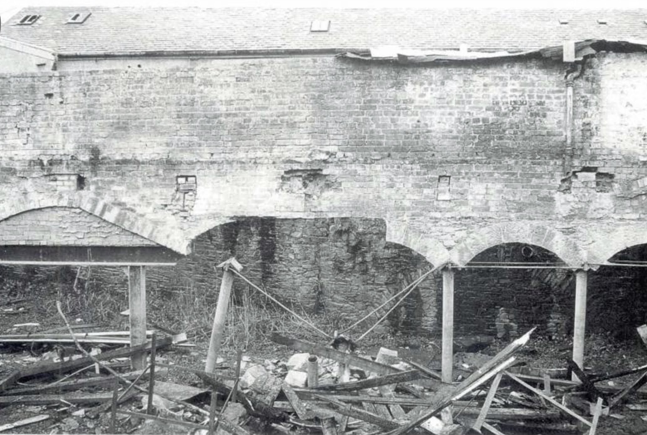
The photograph above shows some columns that I came across at an old industrial site that was to be converted into a modern mixed use development. It was interesting because the columns, which were clearly cast iron, had a cruciform shape rather than the conventional circular hollow form. This is relatively unusual and made them older than their circular cousins.

Today cruciform columns are perhaps even less common than they were in the past. The form is certainly not included within modern codes of practise. This is relevant, because the cruciform shape has an unusual buckling mode that does not apply to other shapes. Subjected to excessive compressive load it will exhibit torsional strut buckling. The modern engineer is familiar with conventional strut buckling and lateral-torsional buckling, which afflict more common shapes, but much less so with torsional buckling. 

This isn’t intended to be a post about torsional strut buckling per se, except to say that torsional buckling reduces the capacity of a column and causes it to fail before other modes of failure. This is why its important to know. The question for this post is why designers in the past would choose a cross section that has a reduced capacity? Did they not know what they were doing?

It is certainly true that modern methods of analysis were not available at the time, though there were column sizing formulae that were used. Typically however, cast iron columns were proof tested and therefore manufacturers and engineers had seen and did understand the failure of columns, at least in a practical or empirical sense.

If we are to understand the existence of cruciform columns we must therefore look elsewhere. We must first understand the material from which they are made and then the way in which they are made. 

Cast-iron has many useful properties. It is strong in compression, it is mouldable, it is resistant to corrosion and crucially it is non-combustible. This last property was considered vital in the context of its early use in the construction of mills. It is well documented that there had been many catastrophic fires.

The challenges of cast iron were its brittleness, its low tensile strength and the tendency for flaws and blowholes to appear. These last two issues are primarily the result of manufacturing.

As the name would suggest cast-iron sections are not rolled or extruded, like other metals. It is like concrete in the sense that it is cast in a mould. Of course unlike concrete it sets hard by cooling rather than by chemical reaction. Also, like concrete it will shrink in the mould, though by a much smaller amount.

Since hardening is by cooling the rate of cooling is vitally important. If one part of the structure cools faster than another then the internal structure of the iron will be different. The faster it cools the better the tensile strength. Similarly, if one part has cooled, and therefore shrunk, while an adjacent part has still to cool and shrink then internal restraint will cause stresses to be built into the column before it has been loaded. In some cases such restraint might even cause fracture during the casting process. The shape of the casting is therefore important.

Another important factor is section thickness. The thicker the member the more likely the surface of the member is to cool before the interior. This would again cause internal restraint and internal stresses to develop.

It follows that a shape had to be developed that was straightforward to mould and allowed iron to flow inside quickly and easily. It had to be symmetrical to promote balanced cooling and the section could not be too thick to stop the interior from cooling too slowly.

The earliest attempts were a crude star shape with a solid centre, however it is not difficult to see that the next logical step would be to extend the points of the star to create ribs, thus forming a cruciform shape. It fulfilled all of the criteria for casting.

Interestingly the ribs were often cast with classical proportions, being wider at the center of the column than at the ends. From this we might conclude that the designers new full well that columns were prone to buckle in the centre and it was an advantage to have more material at that point.

While some modern engineers may look back at early columns and dismiss their designers for having a primitive understanding of buckling behaviour there is of course a deeper truth. The designers from that era understood that columns can buckle, but they also knew about the perils of casting iron and at that point in time it was a bigger factor in the safety of columns than buckling was.

A supplementary question might be why circular columns were not manufactured from the beginning, after all they have a good resistance to buckling and a shape that encourages rapid, even cooling.

I think the answer is probably rather prosaic. Molten iron is extremely hot and is therefore cast in moulds of sand. I imagine nobody had yet worked out how to produce a mould from sand with a void in the middle.

Something else that is perhaps worthy of comment is the relatively large projecting tables at the column heads on which the timber beams are supported. Given what we know about the low strength of cast iron in tension, and by extension flexure, these cantilever projections would appear to be a significant weakness.

In fact there is little evidence of table failure and it has therefore been conjectured that the relatively thin sections cool rapidly after casting and develop a higher tensile strength than is found in thicker castings. 

So there we have it, counter to what you might think, based on a modern mindset, cruciform columns were actually, at the time, a really good idea.


Sunday, March 21, 2021

On Compressive Membranes

System behaviour in fire


Something that isn’t often appreciated is that when a building is designed to achieve a 90 minute fire rating it doesn’t mean the building is designed to remain standing for 90 minutes. This might seem odd, however if we were to pose the question what size of fire is to be resisted for 90 minutes, it is immediately obvious that there is complexity involved. 

In reality a 90 minute fire rating means that the fire resisting components in the building have been tested in a furnace against a standardised fire lasting for 90 minutes. This allows the relative behaviour of different materials to be tested, however it tells us absolutely nothing about how long a real building will survive subject to a real fire. 

This is in part because fire tests treat standardised components individually, however real components are not a standard size and they act as part of a system not as individual elements. If we are being really picky we might also argue that real fires are different to standardised furnace tests.

It follows that if the structural behaviour of a system subjected to fire can be understood then this can be harnesses en lieu of the rather crude prescriptive approach, which is normally applied.

The floors of many modern buildings are constructed by casting a thin slab of concrete on a corrugated metal deck. The concrete is reinforced using a light steel mesh and the metal deck spans between down-stand steel beams. Often metal studs are welded to the top of the steel beams and are embedded in the concrete. This is known as composite construction, because the steel and concrete act together.

To protect the steel from fire the prescriptive approach is to coat it with a fire resting coating, normally intumescent paint. Intumescent paint swells when it gets hot forming an insulating layer, which prevents the steel from over-heating. Without this insulation layer steel looses significant strength and stiffness at approximately 500 degrees.

If, however, the structural system is taken into account many of the beams may not require intumescent paint. This is beneficial because intumescent paint is expensive. 

In the example shown there are primary beams joining the columns together to form a series of identical bays with two secondary beams in each bay. If we were to suppose that the secondaries are unprotected then we can begin to think about the load-path in a hypothetical fire.

As the fire becomes increasingly hot the secondaries will also become hot and will start to loose strength and stiffness. Eventually they will have little residual capacity. When this happens the floor will begin to sag and instead of supporting the concrete floor the beams will hang from it due to the embedded studs. This process is likely to be accelerated by thermal expansion which causes the beams to buckle as they push against their supports.

Conversely the primary beams, located on the column lines, are protected and will remain unaffected by the ensuing fire. They continue to form a rigid frame around each structural bay. As the floor sags it begins to tug on the primary frame simultaneously pulling each side of the bay towards the middle. Much of this work is being done by the light reinforcing mesh embedded in the floor.


This effect causes a compressive ring to be set up in the concrete at the perimeter of each bay. This ring starts to resist the floor’s tugging and allows a point of equilibrium to be reached where the weight of the hanging floor is balanced by the compressive force in the concrete ring. Although the floor has displaced significantly it has not collapsed and has therefore maintained its integrity. The fact that it has displaced significantly is not materially important, as the sole aim is survival. After a major fire a building would not expect to survive completely unaffected.

This load-path means that some of the primary beams must carry additional load, which was previously supported by the unprotected secondaries. This is acceptable, because in the fire case it is permissible for the additional load to be absorbed by the their factor of safety.

It is also worth noting that the required load assumed for most buildings is in fact much greater than the load the floors will ever see. This means the actual factor of safety is normally higher than is assumed in the cold design.


This form of system behaviour is known as a compressive membrane and I have used it successfully to assess the fire resistance of buildings on several occasions. It is a more rational approach to fire safety than the rather arbitrary prescriptive approach, which has been used historically.

Sunday, March 14, 2021

On Shopping Bags & Creepy Buildings

The advantage of squashing a facade


Until we thought better of it a weekly shop meant filling disposal plastic bags, provided by the supermarket, with our groceries. If you only had a few groceries to fetch and you decided to walk or if your car was parked a reasonable distance from the supermarket entrance then you may have noticed a curious property of plastic bags.

When they are initially filled they work rather well, however if the contents of the bag are reasonably heavy, for example  some drinks or a bottle of milk, then by the time you have reached your destination the bag handles have stretched. If the contents are very heavy, and the walk long enough, the handles may even have stretched to the point of breaking.

The interesting question is why this should be so? If the shopping bag performed satisfactorily when it was first picked up, why have the handles stretched by the time you get home? After all nothing additional has been added to the contents of the bag since you left the supermarket. The bag is carrying exactly the same weight as before. Why was it ok to begin with but not afterwards?

In engineering terms this would be described as increased strain at constant stress or in layman’s terms increased stretch without a corresponding increase in load. This is the definition of a phenomenon called creep. Creep happens when the internal structure of a material starts to become rearranged due to the effect of loading. Some materials, like plastic, are more prone to creep due to the nature of their internal structure, however all materials creep a bit under sustained load. It is worth noting that while our shopping bag example is based on stretching creep can also be a squashing effect.

A good example of creep that is more directly related to structural engineering would be the behaviour of old timber floors, which are often bowed in the middle. Another example would be the extension of bridge cables, which must be taken into account in their design. Intuitively it would seem materials progressively stretching or squashing over time is a bad thing. What would be interesting is an example where creep was actually a good thing.

In the late nineties I found such an example thanks to a rather demanding architect [that is not a bad trait in an architect]. He set the challenge of designing a building with a brick facade that was free from movement joints. He viewed movement joints as being ugly, a view with which I had some sympathy. If you haven’t noticed them before now, you will after this post and you will find them ugly too.

The building was shaped like a horse shoe, but with the open end enclosed by a full height glass wall. The perimeter of the horseshoe measured roughly 300 m. 

In case you are unfamiliar with common practise vertical movement joints are normally included in brickwork every 12 meters. You can therefore appreciate the nature of the challenge.

The solution to the problem was rather ingenious. I can say that because it wasn’t my solution. I was a young engineer at the time and still had much to learn. That said having a genius idea is only part of the answer and said genius usually still needs several less experienced, but enthusiastic, engineers to help him work out how to prove the solution will work. I was one of those lucky engineers.

Modern brickwork tends to consist of two thin skins with a cavity in between to keep water out. The two skins are tied together with wire ties. This is the archetypal cavity wall. For most buildings of any size the brick is supported on a floor by floor basis by the building structure and is therefore not load-bearing. The genius part in this case was to go old school and construct a reinforced concrete frame with thick load bearing walls. The concrete floors were supported on corbels embedded in the brickwork.

To understand why this was clever you need to know something about movement joints and several things about brick and concrete.

Movement joints are required because brick expands and contracts. Without relieving joints this will cause cracking. The greater the joint spacing the greater the movement. There are several reasons for brick movement. 

Firstly, bricks expand when wet and contract as they dry, however only part of the expansion is recoverable, as some moisture chemically reacts with the brick and some fills the open pores and will eventually evaporate. Secondly, bricks expand and contract due to temperature variation; they expand when warm and contract when cold. The shade, colour and type of brick affect the magnitude of this effect. 

Conversely concrete shrinks. It does so because the free water, which allows it to be poured, starts to evaporate as the concrete cures. This results in a reduction in volume that is manifest as shrinkage. One of the reasons concrete is reinforced is to control shrinkage and to prevent cracks from developing.


For our building combining the concrete with a soft brick and mortar was intended to pit brick expansion against concrete shrinkage. We worked out that concrete shrinkage could be directed via the corbels to clamp the bricks tight and prevent them from expanding due to irrecoverable moisture movement [the two biggest effects]. These actions are not instantaneous and could therefore be neutralised by creep.

This sounds simple now that it is written down, however at the time we were not sure that it would work. Many hours were spent researching, modelling and in the end testing our solution. In the end we could not make the whole wall work without joints, but the spacing was more than 100 meters.

So there you have it sometimes a creepy building is a good thing. Its never a good thing for shopping bags.


Sunday, March 7, 2021

On Trussed Girders

A curious case of small changes


Several years ago when conserving an important university building I came across some interesting timber floor structures, which I quickly recognised as ‘trussed girders’. I had seen depictions in many conservation text books, one of which is shown below, and was familiar with the form.....or so I thought. It wasn’t until I studied some actual examples that I realised that something wasn’t quite right. 


You can see in the image above that trussed girders are formed from two timber beams, each of which had a groove cut into one side. Into that groove was inserted wrought iron, plate or sometimes hard wood, which was clamped to the timbers with large bolts aligned vertically. The two timbers were also joined by horizontal bolts, which passed through their cross section.

The problem was I couldn’t decipher how such a beam would work, even after reading accounts of how they were supposed to work. Most of the accounts agreed that designers at the time thought they were improving the capacity of the original timber beams, but modern understanding had demonstrated that their only effect was to instil  an upward pre-camber, which helped to control deflection.

My initial reaction had been that the beam was, from an analytical perspective, upside down. If it were inverted I could see that the timber at the top would be in compression and the iron plate at the bottom would be in tension. There wasn’t a particularly good mechanism for transferring tension into the iron plate, but I figured the large bolts at either end would be capable of something. This would be a sort of composite timber and iron truss, which would at least be a nod to the name ‘trussed girder’.

The trouble was the beam wasn’t upside down and inverting the logic really doesn’t work. The iron plates would need to behave as compression struts, which would tend to push outwards and the timber would need to behave in tension. There was literally no observable evidence for how tension would be generated in the timber. Not only that this would invert everything we know about how Victorian engineers thought about timber trusses. Timber was always in compression and the tension joints were always reinforced with wrought iron.

I also thought about what the conservation books had said. I could certainly agree that the arrangement didn’t appear to convey any additional strength, but I also could not work out by what mechanism the arrangement would apply an upward camber.

The only form of adjustment that I could see was the potential for tightening the nuts on the vertical bolts, but I could not imagine how this action would lead to an upward camber.

The answer to my conundrum was only discovered when I consulted a Victorian carpentry manual. The image below is what I found. 


This was interesting for two reasons. Firstly, there were in fact two examples of my inverted logic, but in both cases an iron shoe is visible at the end of each beam, which is clearly capable of transferring thrust into the tension rods, which project through and below the timber beams.

Secondly, the various other examples of the trussed girder all had an iron plate on the soffit of the timber which formed a tie and complete the internal truss. This is also clearly shown in the details at the bottom of the picture.

The most interesting example was the one third from top, again for two reasons. Firstly, the iron struts are torpedo shaped. This has been done because the designer new full well that thin plates placed in compression will buckle at the centre. He has elected a torpedo shape to specifically place material in the middle of the cross-section so that the tendency to buckle is more ably resisted. 

Secondly, there appears to be a pair of joints in the bottom tie member; one either side of the vertical bolts. If these joints were used to tighten the tie, causing it to shorten, this would pull the ends of the struts together and would unquestionably cause the center of the beam to rise i.e. there was a perfectly rational explanation for how camber could be imparted.

Satisfied that I had solved the puzzle of the ‘trussed girder’ my mind turned to why it had been a puzzle in the first place. Did the authors of those conservation books not know what they were doing? Possibly, but I am not entirely sure that is the whole story.

Maybe, just like me, the authors were familiar with the form, because they had also seen it in prior text books, but hadn’t had reason to stop and think about it more deeply. If so this would be a lesson for all aspiring engineers that even textbooks are not always right.

There is however a more intriguing possibility, perhaps the authors had in fact worked on various historic examples that lacked a bottom tension chord. After all this is what I had found; I would not otherwise have started on this journey.

In this case maybe the authors simply concluded the concept was flawed and moved on, after all some of the illustrations reproduced in text books do look quite old. Maybe, because the authors hadn’t seen a tied variant, they figured the original designers simply hadn’t worked it out right.

My suspicion is that trussed girders were rather well understood by the originators of the concept, however structural design was not codified at this time and people often learned by copying. It is entirely possible the someone had tried to copy an original trussed girder based on arrangements they had witnessed. Perhaps they had misremembered what they had seen or had not appreciated the purpose of the tie. Others may then have seen the amended design and copied it too. Before long it is not hard to conceive of illustrations being draw showing the faulty design.

The lesson would therefore be, when borrowing a design concept be sure that you have properly understood it.


Sunday, February 28, 2021

On Treehouse Masters

The Genius of Pete Nelson   


In recent years one of my favourite TV shows has been ‘Tree House Masters’. Sadly I do not believe further episodes are planned. Every week the show followed the exploits of the Nelson Treehouse Company and its eponymous leader Pete Nelson, as they embarked on another building project.

Perhaps Pete Nelson’s greatest genius is convincing a British engineer to enjoy his rather un-British manner. I can’t help it, I find his boundless energy and enthusiasm completely infectious. That said, the thing that a really like, and the reason Pete gets a post devoted to his work, is that despite describing himself as an architect I think he gets to call himself an honorary engineer. Not only are his designs architecturally elegant and beautiful, but the engineering is too. He clearly has a sound understanding of structural load-paths and he unquestionably understands trees and timber.

I rather suspect that Nelson Treehouse has reached the hallowed status that few designers have whereby people want to buy a treehouse with Nelson’s badge on it. They don’t just want to buy a treehouse, they want a Nelson Treehouse.

On that basis Nelson don’t need an endorsement from a blog that nobody reads so I am going to stick to what I know and that is engineering.

Once a grove of suitable trees has been selected to provide columns for the structure it seems to me that the most important factor in treehouse design, at least from the point of view of an engineer, is dealing with movement. 

Trees sway in the wind and like small children have a habit of setting off in different directions at the same time. If this cannot be accommodated then unwelcome stresses will be locked into the construction causing it to become distressed. This is particularly unwelcome if it damages one or more of the supporting trees.

Trees’ ability to sway is important, nature intends them to behave this way so that they can concentrate on growing tall quickly; there is a race to reach sunlight in the forest canopy. Spending their scarce energy reserves growing impossibly large foundations and a thick heavy trunk is undesirable in the race to the top.

The reason this approach is successful highlights the difference between stability, strength and stiffness. Wind blowing on a tree will exert a lateral force, primarily on the canopy, which is the largest part. This force is transferred via the trunk into the roots, which are spread widely like the foundations of a building.

Wind is of course a dynamic load that gusts and billows rather than a constant static force. This is important. As a strong gust catches the tree its trunk will start to yield by swaying. As the structure moves it is not offering resistance to the applied load. Obviously resistance must be achieved at some point or the tree will simply fall over, however swaying buys the tree time while the wind gust diminishes. In this way the bending stresses experienced by the trunk are somewhat reduced i.e. low stiffness attracts low stresses. Or in other words a flexible tree does not need to be as strong as a stiff one to prevent the trunk from snapping. 

Similarly, a flexible tree exerts a smaller overturning force on the root structure, which means that it takes less effort to remain stable than if the tree were stiff i.e. it is less likely to topple the tree.

Another interesting consideration is that tall thin structures tend to be aero elastic. In simple terms this means that when they move in the wind they generate their own eddies and currents that induce further movement in the structure. A feedback loop is set up, which can make them dynamically unstable.

I have a hunch, and it is only hunch, that evergreen trees, which tend to be the tallest trees, retain their covering to help damp out these effects. I realise that someone is going to point me to some very tall deciduous trees; I expect in a rainforest. I haven’t worked out this theory in full, but in my defence I would point to the use of buttresses in large rainforest trees.

Movement is also inherent to the way in which trees age. As they get older they grow taller and fatter. Fortunately trees increase in height from the top and not from the bottom, otherwise treehouses would gradually become higher and the entrance ladder would need to become longer. The bigger issue by far is growth in the size of a tree’s girth. This is really important because of how trees work.

Crudely speaking all of the action happens in the 20 annular rings located closest to the tree’s bark. These rings contain sap wood and they are responsible for conveying the nutrients required by the tree to live. You could think of them like arteries.

If a structure is connected too tightly around a tree’s trunk it will dig into the sapwood as the tree grows and it will begin to choke the tree. There is something all together unpleasant about this. Since the tree is compelled by nature to grow, a tight structure will condemn it to be slowly strangled by that same growth. As this happens it will ooze sap from its wounds. It follows that a less destructive method of connection must be found. 

Nelson have an array of different hangers and connectors that they use to erect tree houses, but they essentially boil down to two types, which have a common method of attachment. A fixed connector that anchors the treehouse and a sliding connector, which permits a treehouse to take vertical support from a tree while allowing the tree to sway horizontally. For each construction a mixture of fixed and sliding connectors must be arranged such that the treehouse is stable while simultaneously being free to move in each direction.

The steel connector attached to the trees is ingenious. The embedded end is of small diameter and has a thread. It is screwed into the tree. The middle of the connector has a larger diameter and is smooth. It is partially embedded in the tree and forms a bearing surface, which increases as the tree grows and envelopes it. The outer section of the connector is also smooth and provides a seating for supporting beams. As the tree grows in diameter beams can slide along the seating without damaging the tree.

There is obviously more to treehouse design than this, but this is the part that interests me the most.

I would highly recommend checking out the Nelson Treehouse Company website or buying one of Pete Nelson’s books. Not because he needs any publicity from me, but because you might just find yourself inspired by one of his fabulous designs.


Sunday, February 21, 2021

On Resistance & Reaction

Surprising qualities of timber in fire


The photograph below is relatively grainy, but is reasonably well known in the field of structural fire engineering. I first came across it at University, however I haven’t been able to determine its original source. I understand that it dates to 1906 and was taken in San Francisco, which could imply that it was linked to the large and devastating earthquake of that year. 


That said, as the sub-title for this post suggests this is not a post about earthquakes. Any relevance to the San Francisco earthquake would be due to the widespread fires that it caused.

That is because the image above pictures a fire damaged roof with steel beams sagging over a supporting timber, which has, by contrast, retained its structural integrity. This is rather interesting, because it defies the common sense view that steel is a superior material to timber in a fire. Self-evidently something else is going on.

For a number of years the timber industry has been promoting timber’s credentials as a green material, however recently I have noticed that it has become rather more active in promoting timber as a good fire resisting material. It has almost become a cliche that timber is better in fire than steel. The photograph above would certainly appear to support this claim. 

I suspect that this new found advocacy for timber’s fire resisting qualities is a response to a number of recent fires; tragically some with significant loss of life.

Yet somehow the facts don’t quite seem to fit do they. Steel buildings don’t burn down and you don’t throw steel onto your campfire to make it burn. It is perhaps a good time to recycle the analogy I deployed in my post titled ‘On Howe Trusses Work’, for this is another case of there being several layers of understanding i.e. a deeper magic.

We should probably start by trying to define what we mean by fire resistance. This is not as easy as you might think. There are normally three attributes that constitute fire resistance. The first is load capacity. This is the ability of a structure to retain its strength and stability in a fire. The second is integrity. This is the ability of a structure to contain a fire and prevent the passage of hot gases through splits, gaps and fissures. The final attribute is insulation. This is the ability of a structure to prevent the transfer of heat from the face of structure exposed to fire to the unexposed face.

The photograph above demonstrates that in respect of load-bearing capacity an adequately sized timber will retain its integrity longer than steel. It is also reasonably clear that timber is a good insulator while steel is a good conductor. Placing your hand on the back of a steel plate placed in front of a fire would hurt more than a sheet of timber, at least to begin with.

Integrity is perhaps harder to judge. Timber will eventually burn through, however steel is more likely to open a gap by distorting. I shall declare this category a draw, as the inference one draws depends largely on the boundaries that are set.

Based on this rather crude assessment we reach the surprising conclusion that timber is indeed more resistant to fire than steel by a score of 2.5 to 0.5. The trouble is that this isn’t the whole story, because ‘fire resistance’ is not the same as ‘reaction to fire’.

Reaction to fire means how easily a material can be ignited and how much it contributes to the growth of a fire. On this measure timber unquestionably fairs worse than steel. Steel is of course classified as a non-combustible material.

It follows that when we talk about fire resistance in engineering we are not actually talking about the common meaning.

Using engineering definitions it may be concluded that during the ignition and growth phase of a fire ‘reaction to fire’ is the more significant material property, however once a fire is fully developed ‘resistance to fire’ becomes more important. Thus, whether steel or timber is considered better depends on timing.

That said, if we must decide then I would choose reaction to fire as more important, because resistance becomes moot if a fire doesn’t start in the first place. That is not to say that resistance isn’t important, because a steel building doesn’t stop someone from leaving a pile of combustible material in the lobby, which could catch fire. 

Another consideration would be the continued existence of historic buildings. It would not be a good idea to simply demolish those which are made of timber, because of the perceived fire risk. We need tools to understand how they will behave when subjected to fire so that mitigation can be established.

There are of course many other examples that could be considered, however these are sufficient to demonstrate that structural fire engineering is a complex business that requires a proper examination of all the relevant factors in a given circumstance.

Incidentally the reason why timber has good resistance to fire is related to its insulating properties. When timber burns it starts to char at a predictable rate. As the charring layer forms it insulates the timber beneath helping to prevent ignition at depth. For this reason steel fixings in timber can be problematic, because they conduct heat into the core of a section.

Since the rate of charring is known an engineer can calculate, for a given duration, a sacrificial thickness of timber that will be charred, while leaving a residual section of timber capable of supporting the required load.

Rates of charring do vary between timber species; the predominant factor being density. Broadly speaking the denser a wood the slower its rate of combustibility and its associated charring rate. 

This knowledge, while sounding modern, is not new. Jarrah, a hardwood [1] was commonly used for railway sleepers in tunnels and on bridges, because of its slow charring response to hot tinders falling from steam engines.

It is worth noting, however, that the relationship between density and fire resistance is not universal. Some woods have chemical contents that make them more likely to burn, however even in such cases density does tend to be the more dominant factor.


[1] it is a common misconception that hardwoods, as the name would suggest, are by definition harder and denser than softwoods. This is a useful general rule, but is not strictly true. Balsa, which is used for model aeroplanes, is a hard wood, while the rather strong pitch pine is a softwood.


Sunday, February 14, 2021

On Accidental Bridges

The robustness of brick walls


I came across this rather interesting photo, which shows the remains of a partially demolished nineteenth century mill. 


The picture is dominated by a large brick wall, which is suspended above ground level. The original load-path for its support appears to have been an arcade consisting of cast iron columns carried on masonry arches. 

To the left of the image one of the arches has been altered. The profile of its voussoirs has been straightened on one side and the arch infilled with modern brickwork. The infill brickwork is in turn supported on a modern beam and post structure, which is likely formed of hot rolled steelwork.

Below the centre of the wall two of the cast iron columns have been pushed over. The one on the left is clearly visible, while the one on the right is a little harder to pick out. Its head can be detected, because it is still connected to the wrought iron rods that would have been used to resist thrusts at its abutments. To the right of the photo the rods can still be seen linking the remaining iron columns.

It is also evident that the masonry arches which would have been carried by the missing columns have collapsed. It is assumed that rubble, which can be seen at the base of the picture, is what remains of them.

What is of course remarkable is that the brick wall continues to stand. It has found a way of bridging between the steel column on the left and the cast iron column on the right. This is interesting for several reasons.

Since the span is roughly equal to the height of the wall it is reasonable to assume that it has achieved this feat by acting as a deep beam. Were the deep beam made of concrete it would be normal to assess it using a ‘strut and tie’ model. This means imagining a triangular load path in the wall. The two vertices of the triangle form compressive struts, which are sat over the supporting columns, while reinforcement in the base of the wall would complete the triangle by resisting lateral thrusts from the inclined struts. An alternative way of considering this model would be to think of it as a tied arch, as the principle would be similar. Indeed, post failure the residual brickwork appears to have formed a crude arch between the column supports.

In this case there is no concrete and no reinforcement, because the wall is made of brick. Brick is good in compression, which would seem to make either an arch, or compressive struts, a viable load path, however there is no equivalent for the reinforcement, which is required to complete the triangle. 

Brickwork is poor in tension and therefore the base of the wall ought to have failed, however there seems little evidence of distress other than the smaller arches giving way to form a larger, if somewhat makeshift arch.

This means the deep beam must, on this occasion, have a different mechanism for resisting lateral thrust. Two options seem plausible, though one seems more likely than the other. 

It is possible that there are rigid load-resisting structures located just out of picture on either side of the image, however if this were the case then there would be no need for the wrought iron ties, which originally held the column heads together.

It seems more likely that the weight of the brick located above the arch supports is sufficient to divert the arch thrusts back to the vertical i.e. it behaves like heavy bridge abutments. Both headers and stretchers can be seen in the brickwork suggesting that the wall is at least a full brick thick and would therefore be relatively heavy.

Looking carefully at the image there is also evidence of pockets in the brickwork, which would have seated beams in the wall. In fact the remains of an I-shaped steel beam can still be seen embedded on the left hand side. It was presumably easier to cut the beam off at the support than to completely remove it during prior alteration works. This may be relevant because the load carried by the wall must have been reduced. This in turn means the thrust is less.

Since two columns are missing we would ordinarily expect those which remain to take 100% more load. For this reason a reduction in load carried by the wall is of significant benefit to the columns too.

So it would seem that a structure whose intended load-path has been compromised has managed to find an alternative load-path demonstrating rather well that structures will exhaust all possible ways of standing before they collapses.

This does not mean that we would necessarily wish to rely on this load path in the long-term, but nevertheless it is a reminder for engineers that there is more than one way of looking at a problem….in this case an accidental bridge.


On Ice Shelf Cracking

Tension Cracks in the Brunt Ice Shelf Yesterday the BBC news website published images showing a large section of the Brunt ice shelf in Ant...