Sunday, August 8, 2021

On Pendentives

A tale of two domes

Perhaps two of the most important domes from antiquity are those belonging to the Pantheon in Rome and the Hagia Sofia of Istanbul. Although the latter is to be found in modern day Turkey, it is of course from the era of Byzantine rule in Constantinople and is therefore of Roman origin.


From their outward appearance the two domes would appear to be similar, indeed how different can the construction of a dome be? Further inquiry would reveal that the materials used to construct the two domes are different. The Pantheon is made of unreinforced concrete, while the Hagia Sofia’s dome is of masonry. Indeed the Pantheon remains the world’s largest unreinforced concrete dome to this day.


This difference is interesting, but in my view is not fundamental to the way in which these two revolutionary structures work. I am perfectly aware of the Pantheon’s oculus, its coffered soffit, the variation in concrete mix over its height, all of which were designed to save weight. These are important details, which are both interesting and worthy of study, maybe I will write about them in some future point, however they are not directly relevant to the subject of this post.

The first thing to note is that classical domes, like later gothic structures, are what I would describe as gravitational or compressive equilibrium structures. That is to say that their structural adequacy is dependent on their shape and not on materials science. This is possible because actual stresses are compressive and sufficiently low that, providing equilibrium is maintained, material strength is unimportant. This makes sense because materials science, at least in the modern sense of stresses and strains, did not exist when they were built. 

Those familiar with the structures in question will no doubt be aware of known cracking in both domes, which might be taken to suggest that there is in fact some material science going on, however as we shall see this is not the case.

To understand the primary difference between the Pantheon and Hagia Sofia, perhaps it is first necessary to explain how a generic dome works. In section domes behave in a similar manner to arches, because their curved profile exerts both vertical and lateral thrust at the seating[1]. Domes are of course unlike arches in the sense that they are 3D structures. This means that the aforementioned vertical thrusts are expressed as compressive meridional stresses extending from the crown of the dome to it’s base. The lateral thrusts push outwards in all directions generating a circumferential or hoop stress that cause domes to spread. It is the way in which the meridional and circumferential stresses are resisted that makes the difference.

Like barrel vaulted structures from the classical period of history the Pantheon is supported on heavy walls that follow the profile of the roof structure, in this case a cylinder, in order to buttress the roof against spreading. Some descriptions I have read speculate a stepped thickening observed at the dome’s base is designed to provide a circumferential tie. Maybe their authors have done more research than me and have data to support this view, however I am disinclined to adopt it based solely on my own intuition that the tensile capacity of concrete, albeit Roman concrete, is too low. Also, if tension were present it would imply materials science is at work to provide the required equilibrium, which is philosophically less satisfying.

It occurs to me that a more elegant solution, which maintains the idea of gravitational equilibrium, would be one where the purpose of the steps was to increase weight at the head of the supporting wall in order to push the dome’s thrust line back into the supporting walls. In essence it would behave, at least in my estimation, like the pinnacle atop a flying buttress.


The dome of the Hagia Sofia is different. It does not find support from heavy buttress walls. Rather it straddles the four corners of a vast open space into which light and air may flood. In character it is a medieval structure whose load paths concentrate the dome’s weight into a carefully defined masonry skeleton. The invention that makes this possible are the inverted triangular masonry panels, known as pendentives, that are located over the four supporting piers. As they spread outwards from their apex a series of four arches are formed on the dome’s perimeter. Together these elements funnel load into the supporting piers where the in plane arch thrusts are buttressed.

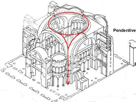
It is evident however that there remains unbalanced thrusts perpendicular to the apex of each pendentive arch. Equilibrium is restored by hemispherical domes that lean in the opposite direction to the dome’s thrust in one direction and buttresses in the other.


And so it is that the dome at Hagia Sofia represents a transition between heavy buttress walls and gothic cathedrals of the later medieval period, whose structures had a more clearly defined order of primary and secondary elements and a more sophisticated understanding of load paths.

Now, to the aforementioned cracks in both domes. Many seasoned observers hold the view that these are the result of past seismic events and differential settlements. Indeed the original dome at Hagia Sofia is known to have collapsed during an earthquake leading to the present cupola being constructed with a higher profile in order to reduce the magnitude of lateral thrusts. 

Nevertheless it would appear that in spite of movement to both structures gravitational equilibrium has been restored. They remain stable, or at the very least, are moving very slowly.


[1] For further information I have written several prior posts relating to the behaviour arch structures.

Sunday, August 1, 2021

On Ice Walking

Just how safe is it?


Today at work I participated in several online meetings, however while we were waiting for colleagues to tune for one of them we found ourselves doing the stereotypically British thing; we talked about the weather.

To be fair the weather was unusual as much of the country, even in the south, had been covered with a blanket of snow. Indeed it had been reported that a portion of the Thames had frozen, which really was an unusual event. This was the predicate for a discussion about whether it would be safe to walk on said ice [you now know this wasn’t written in the summer].

This intrigued me so I set aside a little time that afternoon to try and work out just how safe it would be. This post is about what I found. Now, I should preface what follows by saying that I have absolutely no practical experience of this subject. Everything that follows is a postulation on my part, based on the engineering principles that I believe to be at work. You therefore shouldn’t base your ice fishing trip or curling match on what I have come up with.  

If you must go walking on a frozen lake, I suggest you ask someone who knows what they are talking about and isn’t making it up as they go. Statistically I imagine that such a person is far more likely to have a Canadian accent than a British one. You have been warned!


Ice floats because it is roughly 10% lighter than water. If we are to stand on a sheet of ice we therefore increase its weight making it more likely the ice will sink rather than float. It therefore struck me that the first part of the puzzle ought to be an assessment of how much ice there needs to be to ensure floatation occurs rather than sinking.

A cube of water with sides 1 m long weighs approximately 1000 kg, which means the same cube made of ice must weigh roughly 900 kg. This would imply that for our cube of ice to remain buoyant in water it must carry no more than 100 kg [1000-900].

Now, the minimum recommended thickness of ice for walking is 4 inches; I know because I googled it. That’s equivalent to 100 mm or 0.1 m. 

This means that a block of ice with a square surface that has sides 1 m long, but a thickness restricted to 0.1 m, can carry 10 kg [0.1 x 100]. It follows that if an average person weight 75 kg, then their weight must be spread over a block of ice with an area of 7.5 meters square [75/10] i.e. a square with sides measuring 2.739 m[1].

Everyone knows that ice is a brittle material that fractures rather than bends so that’s quite a large area for load to spread from our feet without something going wrong. I therefore started to think about how the load gets from our feet to cover such a large area and by what mechanisms it could go wrong.

Perhaps our feet would simply punch through the ice like a stiletto heel on soft ground. Such a mechanism would require the ice to shear on a vertical plane passing through the ice, which extends along a perimeter enclosing our feet. The length of the perimeter and the depth of the ice would therefore define the shear plane.

Punching shear yields a stress in the ice equivalent to 0.001 kg[2] acting on every square millimetre of ice on that plane.

The second potential mechanism could result from a shear plane developing across the full width of our notional 7.5 m square block of ice. This time the shear plane being defined by the width and depth of ice. This mechanism yields a stress of 0.0003.

The final mechanism I considered was bending. To transfer load from the feet to the outer edges of our square block the ice must be capable of bending. This is a bit more tricky to calculate, but it results in a stress equivalent to 0.005 kg acting over every square millimetre of ice.

I didn’t really know if any of these figures were significant or not so I got back on google. It turns out that, according to the people who measure such things, ice has a shear strength of 0.06 and a bending strength of 0.07. 

This means that there is a factor of safety against shear failure of 60 [0.06/0.0001] and a factor of 14 against bending failure [0.07/0.005]. I find this quite reassuring, because I don’t actually believe that ice has the strengths I just quoted.

This is not because the diligence of the researchers is at fault; I’m not saying that their work is wrong. What I am saying is that ice is not a manufactured product like steel. It is not made to possess specified properties.

The strength of ice depends on many things. What is the air temperature, did it rise and then fall again during its formation. Is the water fresh or salty? Is there a current or a flow in the body of water that is busy scouring the underside and weakening its structure. Was there snowfall during its formation. Did someone, or something, step on the ice while it was forming thus inducing cracks in its interior.

These and many other issues that I likely haven’t thought of have the potential to change the strength of a given block of ice; its value is therefore not a fixed thing[3]. If I am to walk on ice I would quite like to know that the existence of one or more adverse factors does not completely undermine the strength of the ice I am going to rely on. A factor of 14 sounds good to me. It’s roughly 10 times what I might use for say concrete. That’s about right because I know with far greater certainty what concrete will do.

Obviously if ice melts we are in trouble, but before that point is reached, I have no idea which combination of ice factors might eventually undermine a safety factor of 14. That’s why you shouldn’t take advice about ice walking from someone that’s making it up as he goes.

That being said, my somewhat crude assessment has yielded an interesting conclusion. I started by trying to work out what amount of ice I would require to mobilise to prevent the average person from sinking. My sums therefore exist on just the right side of not sinking, effectively a factor of safety of 1. This assumption eventually yielded a factor of 14 against the ice breaking i.e. in this scenario I am actually more likely to sink than the ice is to break!


[1] I know it would be more realistic to assume a circular perimeter, but I used a square to keep the sums simple. You’ll get over it.

[2] I know that working out stresses in kg is a bit weird, but unless you have a technical background you won’t know what N/mm2 is, or MPa for my European friends, or psi for my American friends. I didn’t want this post to be an explanation of units.

[3] Ice researchers know the strength of ice doesn’t have a fixed value. They provide ranges of values and couch them in temperature limitations and so forth. I picked from the lower end of the scale. 

Sunday, July 25, 2021

On Frocks and Bias

Or why fashionable dresses cling


I like watching movies, but I don’t much care for the process of promoting them or the somewhat cringeworthy awards season that culminates with the Oscars. Writing this in that season, albeit you will be reading this later in the year, I set myself the challenge of finding something Oscars related that involves structural engineering. I assumed that it would likely involve something to do with the staging or set, but eventually I decided to go in a different direction.

Just how do they make those frocks seen on the red carpet hug the body so tightly?

It may not be immediately obvious what figure hugging dresses, of the type worn to award ceremonies, have to do with structures, so your going to need to bear with me. I hope I am not biting off more than I can chew, because I am no fashionista and I don’t know anything about clothes. As always I shall be relying on engineering principles.....


It seems to me that there has never been a time when the human body has not been viewed as art and its form put on display. In this sense not much has changed between the marble sculptures of antiquity to modern day frocks.

That said, one thing that does seem to have changed is that extensive rigging no longer seems necessary to create a tight fit. I suspect that corsets are not terribly comfortable and therefore I expect most ladies welcome their demise.

To understand why we need to understand cloth and how it behaves. We also need to revisit phenomena we have met in a prior post; namely Young’s modulus and Poisson’s ratio. When a material stretches it narrows and when it is squashed it bulges. The amount of narrowing and bulging is directly related to the stiffness of the material; the stiffer the material the less there is. This is why we rarely notice the effect in steel or concrete. Stiffness is the ratio of stress to strain and is known as Young’s modulus, while the ratio of axial stretching or squashing to lateral narrowing or bulging is known as Poisson’s ratio.

Cloth is unlike steel, because its stiffness varies in different orientations. This is due to the way in which it is made. There are two sets of fibres, which are arranged in perpendicular directions. The warp threads are aligned vertically and the weft are weaved above and below. If the cloth is pulled in the direction of the warp there is little stretch in the direction of the tensile force. Similarly the weft threads prevent narrowing in the perpendicular direction. Alternatively, pull in the direction of the weft and again there is little movement in either direction. For this reason cloth is quite stiff in tension, except that is, if it is stretched at 45 degrees to the warp and weft. In this orientation there is considerable stretching and narrowing. Thus, at 45 degrees cloth has a low Young’s Modulus and a high Poisson’s ratio.


A useful analogy would be to compare the stiffness of a structural grid formed of perpendicular members with a lattice formed of diagonal members. Due to rotation at the joints the lattice is poor in tension, but good in shear, while the perpendicular grid is good in tension, but poor in shear.


Now supposing a dressmaker were to arrange and cut the cloth for a dress such that the warp and weft were aligned at 45 degrees to the vertical. I gather this is known as a bias cut. In such circumstances the self weight of the dress would place the cloth in tension, which would cause stretching in the vertical axis and a corresponding contraction in the perpendicular direction. 

Self-evidently the noted contraction would cause the dress to hug more tightly around its wearer. 

I am quite sure that dress makers must have lots of crafty tricks to enhance this effect. Perhaps they use thicker material, folds or stitching to increase the weight of the dress in certain locations or perhaps they vary the composition of the cloth by using threads of different stiffness or looser weave.

I have no idea if these are actual things or not, but they do seem to be reasonable suppositions based on the need to minimise Young’s modulus and maximise Poisson’s ratio. 

I don’t suppose dressmakers communicate in terms of Young’s modulus & Poisson’s ratio, but to make their dresses work as they do I suspect they do have a rather good empirical understanding of cloth. 

All this means that while I have little time for red carpets and awards ceremonies I can at least admire the skill of the dressmaker and their intimate knowledge of fabric. Whether they know it or not the figure hugging designs that have replaced laces and corsets rely on sound engineering principals.


Sunday, July 18, 2021

On Grass & Buckling

Why you shouldn’t walk on a frosty lawn

An interesting thought that hadn’t struck me before is why it is possible to play sport on grass without it being ruined. I am not suggesting that sports pitches don’t suffer from wear and tear; self evidently they do. After two weeks of tennis in the summer the courts at Wimbledon are not in the same condition they were at the start of the tournament. Similarly, after a season of football or rugby pitches around the country need time to recover, albeit pitches today fair better than they did in the past, but that’s not really what I mean. How is it that sport can be played on grass at all? 

It takes no effort at all to pluck a blade of grass and almost none to tear or cut it, how then can we walk on grass without damaging it let alone run and jump? I think the answer is to be found in a structural principle known as Euler[1] or Strut buckling. Euler buckling is a special form of compression failure, which applies to slender structures and is named after Leonhard Euler who sorted out the mathematics. Slender structures are those, which are thin relative to their height.

When a squat structure is subjected to compression it will fracture and split if it is made of a brittle material. Alternatively, if it is made from a ductile material it will bulge and deform, however a slender structure will buckle before any of these states are reached.

Buckling is essentially the point at which a structure subjected to compression gives way due to a rapid increase in lateral deflection. The reason deflection increases rapidly is because the onset of buckling instigates a feedback loop.

When buckling begins the structure is displaced laterally, which causes the compressive load it carries to be applied eccentric to the line of support. As we have learned in earlier posts an eccentric force generates a bending moment, which causes increased lateral displacement. Thus the feedback loop is set in motion.


Euler’s work teaches us that the load at which buckling commences is directly proportional to the stiffness of the structure and inversely proportional to the square of its length. This tells us two important things:

Firstly, doubling the stiffness of a structure will double the buckling load, whereas doubling its length will reduce the buckling load by three quarters. The length of the structure is therefore the most significant factor.

Secondly, providing the material is ductile and will therefore remain elastic, its strength plays no role in Euler buckling. This means that once the compressive load has been removed it will recover and return to its original shape. For those who are interested elasticity is covered in a prior post, On Ductility.

These are the properties which make walking on grass possible. A blade of grass has a low material stiffness and is tall relative to its thickness i.e. it is slender. For this reason when you step on grass the blades simply buckle elastically and then recover when the foot is lifted. It is also worth noting that grass grows from the root rather than the tip so any damage that does occur can be repaired from below the damaged part.

It is often said that you should not walk on a frosty lawn. In light of our buckling logic the reason for this becomes clear. Grass, being a plant, is made or cells which contain water. I am sure biologists would put it better than this, but I think that’s pretty much the case. When a frost sets in water contained in the cells will freeze and make the normally flexible blades of grass brittle. It follows that if you were to step on a lawn in this condition the frozen blades would no longer be elastic and instead of buckling they will fracture. Thus permanent damage is done.


So that’s my answer; sport can be played on grass, because each blade is a small slender structure that behaves according to the rules of Euler Buckling. I suspect that the normal wear and tear that we see on sports pitches is primarily due the lateral movement of feet, which would presumably apply horizontal shears that tear and rip at the buckled blades. That said, this cannot be the dominant behaviour or pitches would become rather more damaged than they actually are.


[1] Pronounced Oiler

Sunday, July 11, 2021

On San Petronio

Gravitational equilibrium & the square cube law


‘Gulliver’s Travels’ is a classic of English Literature written by Jonathan Swift in 1726. It is intended to be a satire of human nature and ‘travellers’ tales’. In the book its protagonist visits the fictional countries of Lilliput and Brobdingnag. The citizens of the former are 12 times smaller than Gulliver and in the latter they are 12 times bigger.

Of course every reader of the book knows that Lilliput and Bribdingnag are fictional, but perhaps fewer might realise that they are necessarily fiction in any possible world that follows the same physical laws as our own. The reason for this is described by the square cube law, which was first attributed to Galileo.

According to this law the size of things cannot be indefinitely scaled up, because the physical properties of objects change as they increase in size. Consider a cube with sides one unit long. If we were to double the length of each side then the surface area of each face will increase from 1 to 4 units. The volume of the cube, and by extension the quantity of stuff from which it is made, increases from 1 to 8 units i.e. doubling the linear dimensions causes the surface area to be squared and the volume of stuff to be cubed.

In other words the rate at which the volume and weight of an object increase with size is greater than the rate at which its linear dimensions and surface area increase.


Conversely, the strength of things, normally expressed as a limiting stress, is independent of size
[1]. It follows that as things become larger, while retaining their original proportions, they will eventually reach a point where they can no longer support their own weight. This places an upper limit on how big things, including people, can get.

This is a vexing problem for modern day architectural students, who are surprised to learn that the model they have spent hours building does not prove that the structural gymnastics their design requires are viable in the real world.

There is of course an exception to the square cube law, though not a true exception. The square cube law does not cease to work, rather it is not discernible within the normal range of scaling for certain objects.

An example of such an object from the natural world would be a mountain. An equivalent structure form the man-made world would be a pyramid. Both structures come from a class of things that share three key ingredients. Firstly, they are both made of stone, which is a natural material with a very high compressive strength and low tensile strength. Secondly, they are both compression structures that assiduously avoid tension. Thirdly, they are stocky and solid structures. Not solid in the sense that they are strong, though that is indeed true, but solid in the sense that they are not hollow. The implication of being stocky and solid is that they are not prone to buckle, as a slender or thin walled structure is. A second implication of stockiness is a large cross-section, which implies low stress.

These then are the ingredients for subverting Galileo’s square cube law and within the class of things which have these ingredients there is a group of structures that does so with a style and panache that is difficult to surpass. They laugh in the face of the square cube law.

I am of course talking about gothic structures; those great stone cathedrals of the late medieval period with their quadripartite vaults and flying buttresses. I am often asked, mainly by my dad, how it was that medieval masons created such structures in the absence of modern structural theory. The stock answer is that they used rules of thumb, but for me there has to be more to it than that.

How on earth did they manage to design structures, using rules of thumb, that modern analysis shows us to have near perfect proportions. Rules of thumb are intended to apply generally, but must necessarily be derived from the particular. The further a design departs from the particular the less useful a rule of thumb is. 

Gothic structures do have similarities, but there is also great variety in their design, which ought to make rules of thumb less helpful.

Perhaps the answer to this dilemma is to be found in a process of trial and error. While there was undoubtedly a role for trial and error I am not convinced that it played a central role, at least not in the commonly understood sense. I hold this view for several reasons:

Firstly, most cathedrals took hundreds of years to build and though master masons may have worked on several, they would not, in their own lifespan, have time to learn all the necessary forms by trial and error. This brings us back to rules of thumb. Secondly, while there is evidence of design evolution over time there is relatively little evidence of major failures, which is odd given the innovative, and often spectacular, designs adopted. Furthermore, when known failures occurred they were often, though not always, associated with abnormal events like earthquakes or phenomena external to the structure like differential settlement.

We therefore have much evidence of trying daring new things, but scant recorded evidence of failure [2]. This is not entirely a surprise, because cathedrals are expensive and their proprietors were not stupid. Master masons would not have been in charge for long if their structures kept collapsing.

To find a satisfactory explanation I think we need to return to the square cube law. If a structure could be designed to subvert the square cube law then a successful pattern would be successful at any scale. It follows that if you could demonstrate a particular form of structure would stand using a small model made of wood then it would also stand if it was scaled up to full size. 

I do not know whether masons understood that they were subverting the square cube law. I suspect that they didn’t, but I do think that they understood perfectly well the load-paths and principles that were necessary to keep a stone structure in equilibrium. I think they fully understood that tension was the enemy and that gravity must be harnessed to maintain compression in all parts of the structure. 

They were specifically designing structures to achieve gravitational equilibrium and they were doing it by experimentation with scale models. They then used rules of thumb, derived from these models, to scale up their findings to full size structures.


Happily for the masons this methodology was just perfect for avoiding the square cube law, whether they knew it or not, and in this way spectacular and innovative designs could be realised without needing to know anything about materials science, stresses or strains.

While this theory involves a heavy dose of speculation it is not without evidential support. For example, we know that Antonio Vicenzo the designer of San Petronio church in Bologna commissioned a model of brick and plaster at circa one eighth scale. It was around 19m long and 6m high. I expect that it was used to convey the design to its proprietors, but I don’t think it is too great a leap to posit that it might also have played a role in the church’s structural design.


[1] I accept that all bets are off at the atomic scale, but we don’t normally consider atomic forces when designing building structures, bridges and the like.

[2] I know that absence of evidence is not evidence of absence, nevertheless evidence is sometimes notable by its absence, particularly when there might be a reasonable expectation to find some.


Sunday, July 4, 2021

On Britannia Bridge

An empirical masterpiece


When I studied engineering at university one of the structures that was frequently put forward by Professors, as an excellent example of structural design was Britannia Bridge. Throughout my time at university and probably for a time afterwards I didn’t really understand why. It didn’t seem a particularly great design to me. I don’t suppose for one moment that was my Professors’ fault; I had good teachers. I suspect it was more likely that I wasn’t paying sufficient attention.


Though I was unquestionably wrong, if I give my younger self the benefit of the doubt, my view was not entirely without merit. Firstly, I had not seen lots of other bridges old or modern that resembled Britannia; suggesting that despite its supposed brilliance few saw fit to copy it
[1]. Secondly, passing steam trains through a tubular structure, as Britannia did, didn’t seem like a good idea to me. The smoke and soot must have been pretty unbearable. Furthermore, the integrity of the bridge was compromised by fire in 1970, which brought about its eventual demise. It therefore failed in its primary purpose of carrying trains from Wales to Anglesey. 170 years of service is by most accounts rather good, but I reasoned this was luck. What would have happened had the fire occurred earlier in its life? 

Notwithstanding all of this, Britannia Bridge was, in my humble opinion, ugly. My architect friends might well quip that this is exactly what to expect from a bridge designed by an engineer. I beg to differ, but that debate is for another day.

Having got that historical baggage off my chest I am now, as you might have guessed, wholly convinced of Britannia’s brilliance and it’s aesthetic has sort of grown on me. I’m not saying it has become easy on the eye; rather an appreciation of how it works and how it came to be has resulted in a greater appreciation of its aesthetic.

So why did I change my view of Britannia’s structural design and what was it that persuaded me? Much like students today, my younger self lacked an appreciation of context and when judging the achievements of the past context is everything.

Thomas Telford, the first president of the Institution of Civil Engineers, completed the Menai Strait suspension bridge in 1826. At that time it held the record for the longest suspended span in the world and it is an elegant and beautiful bridge. That said Telford’s masterpiece [perhaps the subject of a future post] was not without problems. It suffered aerodynamically and was damaged on several occasions before being stiffened. 

When Robert Stephenson was faced with the problem of bridging the Menai Strait for the Chester & Holyhead railway a suspension bridge, like Telford’s, was not considered stiff enough to carry the weight of steam locomotives [the suspension form was still in its infancy].

The obvious answer would have been to construct intermediate piers from which arch centerings could be erected, however the currents in the strait were considered to be treacherous and therefore the Admiralty insisted that there be no obstructions placed in the channel, which would make it more difficult to navigate. The only place an intermediate support could be found was at Britannia rock, which was located almost halfway between either shore. 

An alternative idea was to construct an arch on centring built from floating pontoons, however this was also ruled out as there would have been insufficient clearance for ships near the abutments at high tide.

Since a suspension bridge was deemed too flexible and the Admiralty’s intervention had ruled out an arch, Stephenson had to invent something altogether new. 

To achieve the required strength and stiffness Stephenson had some notion that the answer would involve creating large wrought iron plate girders by riveting. He later settled on the idea of a wrought iron tube through which the trains would pass. He had originally thought of the tube as being suspended from chains, but decided instead that it should behave as a hollow beam spanning from end to end.


In 1845 there was no structural theory that could be used to design Stephenson’s hollow tube, albeit British engineers had little time for the theories of their European neighbours. This was not unreasonable as theory was unable to justify the structures that British Engineers were already producing at that time. Telford himself was on occasion disdainful of theory, his Menai Bridge was entirely justified by rigorous testing of its components.

Stephenson turned to William Fairbairn, who was known for his investigation of iron and his experience of ship hulls, which seemed analogous to his hollow tube idea. He engaged Fairbairn to investigate a hollow tube design by conducting experiments on scale models.

Fairbairn realised however, that extrapolating behaviour observed in models to full scale was not straightforward. He therefore recommended Eaton Hodgkinson to Stephenson for the purpose of deriving empirical relationships from his models that could be used to size the bridge. We have of course met this pair before in a prior blog post ‘On Fish-bellies’. 

And so it was that three great pioneers Stephenson, Fairbairn and Hodgkinson set about designing Britannia bridge.

Amongst their findings the trio discovered the mechanism of plate buckling, which overturned the idea that wrought iron was weaker in compression than tension. They also discovered that rivets work by clamping and friction, when previously it was assumed their behaviour was governed by dowel action. They looked at the effects of continuity over an intermediate structural support, which enabled a more efficient design to be realised. They also explored thermal movements and wind effects. Their collaboration was a remarkable piece of work.


That said, it wasn’t all plain sailing. They argued about whether suspension chains were in fact required so late into the process that the bridge piers had to be built full height just incase they were needed. Fairbairn took the position, based on his experiments, that the chains were not required, while Hodgkinson, based on the empirical theory he was developing, took the position that they were. In the end Fairbairn’s argument prevailed; Stephenson omitted the chains and Fairbairn was proved right. 

The resulting bridge was a mixed success. It performed as intended, however it was exceedingly expensive, owing to the cost of iron in the mid nineteenth century. This is probably the main reason its form was not adopted more widely. Nevertheless, Stephenson’s design methodology was exceedingly influential, as were the empirical insights gleaned from Fairbairn’s models.

In this sense Britannia Bridge is archetypal of the empirical approach to design that was practised by British Engineers at that time.

Ironically the fire, which caused its eventual demise in 1970 was caused by ignition of the wooden roof covering that was later added to protect the bridge from corrosion. It wasn’t even part of the original bridge, so my younger self got that completely wrong too!


[1] In a very pure sense this isn’t strictly true, because modern bridges do make use of box girders, but not in the same way as Britannia. 


Sunday, June 27, 2021

On Lunes & Cracks

Conserving St Peter’s Basilica


The dome of St Peter’s Basilica in Rome is one of the most recognised structures in the world. It was completed around 1590 and was conceived by the genius Michelangelo. There are many reasons why it is special structure, but perhaps the most important is amongst the least well known.

By around 1680 cracks were being reported in the dome, which unsurprisingly caused some to question its safety. Concerns were exacerbated following an earthquake in 1730. Meridional cracking, associated with a dome’s tendency to spread at the base, was well known in the sixteenth century and therefore, following a detailed investigation, a recommendation was made to supplement the existing wrought iron hoops, which were intended to prevent spreading, with three or four more.


It would seem that the Vatican had travelled a distance since Galileo’s heresy trial and the incumbent Pope Benedict XIV, unlike many designers and practitioners of the day, was impressed by the progress made by scientists and mathematicians of the day. He therefore commissioned three of them; Thomas Seur, Francois Jacquier & Roggiero Boscovich to examine the subject. The publication of their findings in 1743 was a seminal moment for Structural Engineering, because they had based their conclusions on a mathematical analysis of the dome. It was the first known occasion when this was done in any meaningful way. Their approach included a model of the dome’s weight, its materials and two different behavioural scenario’s. The method they adopted for combining this information would today be called ‘virtual work’.

They concluded that the existing iron rings embedded within the dome were insufficient to prevent spreading and that the dome would collapse. They therefore proceeded to calculate the number and proportions of additional rings. This was of course a safe recommendation, however it overlooked the rather important fact that the dome had not in fact collapsed and was very much still standing.

Though they were three of the smartest mathematicians of their day they had made the same basic error that almost every graduate engineer makes at some point. They had placed their confidence in their model over what they could see with their eyes. One of the most important truisms of structural engineering is that a structure will remain in place until it has exhausted every possible means of standing. Consequently, if a mathematical model says a structure will collapse, but it stubbornly refuses to do so, then one is obliged to conclude that the model is wrong and not reality.

The presiding committee responsible for the church’s upkeep did what committees often do. They ignored the expert report and continued to monitor the structure. Benedict was also dissatisfied, but wished to persevere with a scientific approach. He commissioned a new study by a different expert Giovanni Poleni. 

Poleni criticised aspects of the first report and tackled the problem with a different approach. While he conceived his own mathematical model, Poleni was also aware of Robert Hooke’s work on the stability of arches, which is described in an earlier post [On Balloons, Chains and Arches]. He therefore imagined the dome to be split into a series of lunes each of which rested against an opposing lune on the other side of the dome. He then used a physical model to demonstrate that the line of thrust for a pair of lunes lay within the depth of their cross section and would therefore meet Hooke’s criteria for a stable arch. By this reasoning the whole dome, being a series of balanced lunes, would be stable in spite of its meridional cracks.

Nevertheless, Poleni also recommended four additional wrought iron hoops, which were installed in 1744. A further hoop was added in 1747, when it was discovered that one of the originals had in fact fractured.

While the application of mathematics to structural engineering problems, which was pioneered by Seur, Jacquier and Roggiero, would prove successful in the long run it is not difficult to see why it was unsuccessful to begin with. 

While mathematicians and scientists had been publishing treatise on engineering subjects from the early eighteenth century, architects and engineers of the day were unacquainted with mathematical argument and treatise were therefore largely ignored.

A second, and perhaps more significant issue, was the relative maturity of the respective disciplines. Eighteenth century mathematical models, though brilliant in their conception, were no match for 1,000 years of engineering experience, which had refined and optimised known structural forms about as much as it was possible. The only conceivable  advantage for science would be for the conception of structures for which there was no precedent.

This dichotomy caused a divergence in engineering practise between Britain and its European neighbours. While France and Germany forged ahead with academic schools of engineering Britain largely adopted an empirical approach. Unsurprisingly the continental Europeans produced more impressive academic works, however Britain prospered with its empirical approach, which produced closer alignment with the real world and therefore greater efficiency.

Britain’s engineers did not dismiss theoretical works, because they were less intelligent or less capable. They simply knew that the best academic theories of the day could not get close to matching the empirical approach they were pioneering.

There is a lesson in this for the modern engineer. Modern codes of practise are becoming increasingly academic and less practical. It is not clear to this engineer that the additional effort required to use them yields a justifiable benefit. I am also quite certain that as in the eighteenth century some modern methods are less efficient than the empirical methods they have replaced.

In some circles our profession needs to rediscover the once obvious truth that a theory, which does not match past empirical experience, is not a good theory.....particularly when it is more complex to use than its predecessor.


On Ice Shelf Cracking

Tension Cracks in the Brunt Ice Shelf Yesterday the BBC news website published images showing a large section of the Brunt ice shelf in Ant...