Sunday, November 29, 2020

On Pile Caps

Different ways of tackling the same problem


The soil beneath some buildings is of insufficient stiffness to support the weight of heavy buildings. The solution is to carry their weight on piles, which extend deep underground. In some cases the piles are embedded in rock and are known as end bearing. In other cases rock is located far below the ground surface and therefore piles rely on generating friction with the ground. 

When more than one pile is require to carry a column’s load it is necessary to construct a bridge between them on which the column may sit. This concrete bridge is known as a pile cap. Pile caps are therefore important structures that lie unseen and unnoticed below ground level.

Since they are unseen pile caps are simple functional structures without a care for visual taste or aesthetic consideration. They are amongst the simplest structures an engineer can design.....or so you might think.

The real world turns out to be more complicated than that, because nobody is entirely sure how pile caps work. This is a surprising fact, even for some engineers, who assume their well worn methods of design represent absolute truth.

This should not be a surprise, because most will know that there are two standard methods of design; the so-called ‘strut and tie method’ and the ‘beam theory method’. It is curious that some see no significance in the fact that two methods exist. Fewer still seem to realise that we are not limited to two; there are in fact many more ways of considering the problem. 

When you appreciate this you can see different ways of analysing all sorts of problems. It liberates your mind from the sort of engineering that cannot see past the prescriptive methods set down in text books and codes of practise. It gives the engineer licence to explore other load-paths and freedom to innovate. That said, let’s not get ahead of ourselves.

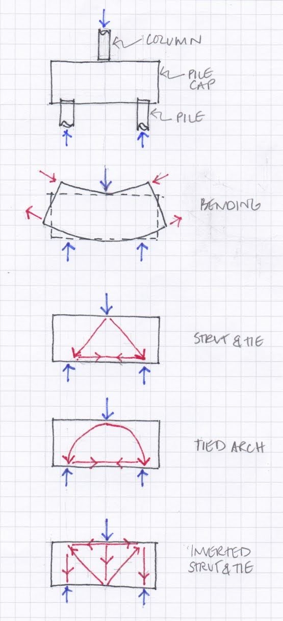
Perhaps one of the simplest structures conceivable is a column supported on two piles with a two-pile cap distributing the load evenly. We know the cap distributes the load; the question is how?

Let’s look at ‘beam theory’ first. Using this approach we assume the cap is a large beam made of reinforced concrete, which behaves much like the joists in a house. As the beam is loaded it begins to bend i.e. it takes up the form of a curve. When it does so the top surface necessarily becomes shorter and the bottom surface becomes longer. Self-evidently the surface that is becoming shorter is being squashed and is therefore in compression and the surface that is being stretched must therefore be in tension.

Every engineer knows that concrete is strong in compression, but weak in tension. In fact concrete will begin to crack when the tensile forces are still quite small. For this reason concrete is reinforced with steel bars, which are strong and resilient in tension. Bars are placed into the zones where tension exists. In this case at the bottom of the pile cap.

Now let’s look at the alternative ‘strut and tie’ model. Using this approach the engineer assumes the existence of an imaginary triangle with it peak touching the top surface of the cap, just below the column, and its base stretched over the piles below.

It is not difficult to imagine fifty percent of the  column’s load traveling down each leg of the triangle by means of compression. These are the eponymous struts. One might be tempted to assume that since the load travels by compression there is no need of reinforcement, however we must pay close attention to the angle between the two struts. Since they are not vertically aligned our imaginary triangle struts must have a horizontal component to the force which they carry. This horizontal force wishes to push the two legs apart, much like the force that causes a house of cards to spread and fall.

To prevent our imaginary triangle from spreading there must be a tie, which is conveniently provided by the bottom chord of the triangle. Again, since concrete cannot resist tension, steel reinforcing bars are inserted into the bottom of the concrete. Curiously, the quantity of steel that this approach requires is different to that derived by beam theory.

Now that we have examined the two ‘normal methods’ we can of course try some other methods. Instead of an imaginary triangle, why not assume an imaginary arch with a reinforced tie at the base?

Another approach would be to turn the ‘strut and tie’ model upside down and assume an inverted triangle. This is an interesting, if slightly convoluted, concept, which would be tricky to build, but is perfectly tenable. In this example tension bars would extend from the top corners of the pile cap down to the middle of the bottom surface. The legs of the triangle would be loaded in tension and would therefor pull the top surface together forcing it into compression.

The reason this approach is more convoluted is because the peak of the imaginary triangle does not sit directly below the column and its base does not sit directly above the piles. To complete the load-path it is therefore necessary to imagine a strut in the middle of the triangle that transfers load from the column down to the peak of the triangle. Two more struts are requires, one at either side of the base to transfer load into the piles.

Of course, if we can invert the ‘strut and tie’ we can also invert the ‘arch model’. For similar reasons this is also a tricky arrangement to build, but perfectly viable.

We now have four methods by which we could potentially transfer load from a single column into two piles. There are many more. For example, instead of a ‘strut and tie’ we could consider an imaginary truss. When we do so it is not difficult to imagine the many and varied ways in which the internal chords of the truss might be arranged.


So which method is the ‘real’ load path by which the pile cap actually transfers load. The truth is it doesn’t actually matter. So long as the engineer has designed at least one way in which it could work the structure will stand. The contractor who has to build it may not see it that way, but for the purposes of this exercise that does not matter. The point is that for even the simplest of structures many possible load-paths exist and that is an interesting conclusion.

Perhaps more interesting still is what happens when we consider a single column and a single pile. Surely that has to be straightforward, right? I’ll answer that question next time.

Sunday, November 22, 2020

On Imaginary Cantilevers

Unraveling the mystery of pencheck stairs.


Staircases hardly seems like a topic to ignite much interest, however there is one type of stair that is particularly interesting and has a bit of a mystery about its load-path. So mysterious that no one can actually agree what to call such stairs. ‘Cantilever stairs’ is the most common name, but ‘hanging stairs’, ‘geometric stairs’, and ‘stairs with a void in the middle’ have all been tried too. In this post I am going to run with the Scottish term ‘pencheck stairs’, but before I do I am going to start with the one before.


‘Stair with a void’ is an important description, because until Palladio coined it in ‘Quattro Libri dell’Architettura’ during the sixteenth century, stair treads generally bridged between two walls. The concept of supporting a stair from one side only, so that light could flood into the stair well from above, was completely unknown...or at least we have no evidence of it.

Pallidio’s concept was taken to new heights by successive exponents and some of our grandest buildings are adorned by elegant stone staircases with narrow wedge like treads that seem to float from bottom to top. Then, at some point in the past, probably the early twentieth century, Pallidio’s concept fell out of fashion and somehow engineers forgot how they work. This remains the case for some engineers today.

One thing we do know is that many nineteenth century examples have been investigated and it turns out the stone treads are embedded only 4.5 inches into the supporting wall. That’s effectively the width of one brick.

This simple fact tells us something important about pencheck stairs. 4.5 inches is completely insufficient to support cantilever behaviour. Evidently pencheck stairs do not, as one would suppose, cantilever. Their load path is therefore a structural mystery. 

I know the load path is a mystery, because I have seen several examples where a worried engineer has added a steel beam below the outside edge of the treads, simultaneously ruining the stair’s aesthetic and their own engineering credibility. 

Once it has been recognised that pencheck stairs do not cantilever their secret can be understood in terms of a load path that consists of three component parts. 

The first part is quite simply load transfer through bearing. The front of each step sits on the back of the one below transferring load progressively from the top of the stair to the bottom. The second component of the load path is torsion. Since load is transferred from above into the back of a tread and is transferred out of the same tread at the front a load ‘couple’ is formed i.e. the front pushes down on the tread below and the back resists the tread above by pushing back up. This combination of forces is what generates torsion.

Torsion is of course resisted by embedment in a brick wall. All the brick need do is prevent the stone tread from rotating. This is why embedment can be so shallow. 

Together bearing and torsion are quite sufficient for a stair to stand without further assistance.


The third load-path component is only necessary when stair treads have a particularly slender profile; sometimes a mere wedge. It is developed by small rebates at the back of each tread, known in Scotland as penchecks. In this arrangement the toe of each tread interlocks snuggly with the pencheck below.

Given its size one might be forgiven for assuming the presence of a pencheck is somewhat superfluous, however closer examination of the load-path reveals this is far from the case. It is in fact crucial.

Let us first revisit the style of stair that has no pencheck. It is self-evident that since each tread bears on the one below the cumulative load on the final tread is the sum total of all the treads above i.e. the load carried by each tread increases the closer it is to the bottom of the stair. It follows that the torsional component is also greatest at the bottom of the stair. This is fortunate because, unless there is a door or window, the weight of masonry available to resist torsion is also greatest at the bottom of the stair.

We are now ready to consider the effect of penchecks on the same stair. Since they are interlocked, rotation of a tread will cause it to push into its neighbours above and below. While the top surface pushes against its upper neighbour the bottom surface pushes against the lower one. These pushing forces are in equal magnitude and opposite direction. In effect we have created a horizontal load ‘couple’, which acts against the tread’s desire to rotate. This effect passes from one tread to the next; both up and down the flight. At the top of the stair the cumulative push is met by the top landing. If the landing is secure, and cannot move, then the upward thrust is resisted. Similarly, if the base of the stair is secured by the bottom landing then the downward thrust is also resisted.


In order to simplify this part of the load path we can make a conservative assumption. All of the horizontal thrust generated by the penchecks is assumed to be resisted by the landings i.e. no benefit is taken from embedding the treads within a brick wall.

The effect that this has is profound. It creates an overall load ‘couple’ between the two landings that results in a uniform torsion over the length of the stair. This in turn reduces the torsion due to part two of the load path by half. Perhaps the best way to understand  this conclusion is to review the forces visually.


The top diagram depicts the torsional force in the treads without penchecks. It is minimal near the top of the stair and maximal at the base. In the middle diagram we can see a uniform torsion due to pushing forces generated by the penchecks and resisted at the landings. 

We can combine these two diagrams by subtracting one from the other, as shown in the bottom diagram The net clockwise torsion at the base of the stair is reduced by the same amount as the anti-clockwise torsion at the top is increased. The net torsion on the middle tread is therefore zero.

The net torsion transferred into the brick wall is also significantly reduced as the treads have now taken on much of the work themselves. It is this effect that allows stairs with more elegant and slender cross sections to be built.

It is accepted that part three of this load path has been resolved in a simplified manner. The true distribution of load between wall and tread is difficult to calculate, as it is sensitive to the relative stiffness and contact between all the components. Nevertheless, no matter the precise distribution of load, in qualitative terms the principles hold good and reveal to us the secret of the pencheck stair.

Now that we have solved the easy bit let us return to the difficult part. What should we call such stairs. I don’t like ‘cantilever stair’. I like the fact that there is a mystery about how such stairs work, but ‘cantilever’ is not mysterious; its just plain wrong. I am sympathetic to ‘stair with a void in the middle’, as it is an historic description that credits Palladio. That said, I can’t run with this, because people are no longer surprised by a stairwell with a void. Time has robbed this potential title of its power to impress. ‘Hanging stair’ is like ‘cantilever’ stair; it’s just plain wrong. ‘Geometric stair’ is bland and without any useful meaning. ‘Stairs with one sided support’ has been proposed. It is technically accurate, but somewhat wordy, and therefore unlikely to catch on. 

No, I am going to stick with the Scottish description ‘pencheck stair’. I like this for two reasons. Firstly, it recognises the crucial role played by those little rebates. Secondly, hardly anyone in Scotland, let alone anywhere else, knows what ‘pencheck’ means, thus the sense of mystery is preserved. 

Sunday, November 15, 2020

On Conservation Principles


In the past homes were modest, places of work were agricultural and our grandest buildings were temples, cathedrals and palaces. During the industrial age our cathedrals became places of work; great factories and chimneys filled the skyline. Today residential towers exceed in height the tallest spires and chimneys, while in the suburbs two floors are normal. Work is now knowledge based, requiring data centres instead of machine halls and factories, and cathedrals are home to sport.

It follows that, while aesthetic taste changes and is subjective, there is also a class of building that contains in its fabric a record of human activity; our culture and our endeavours. It is self-evident that both types of building should be preserved.

That said, people do not want to live and work in museums and therefore buildings must, as they always have, adapt to change. This requires those of us who work with such buildings to see ourselves as custodians. What we receive from the past we must make fit for the future, so that there remains a living record of that which has passed from memory.

Although we must make every effort to honour evidence of the past and to preserve the character and history of a building, we need not be afraid to repurpose it or to upgrade its fabric and systems.

If we have worked hard to understand what the original designer had in mind, and any subsequent alterations, we will appreciate what is special and individual about a building’s character and personality. What must be preserved and what may be changed. Of course, it is not only important that we preserve the significant parts, how we do it is also important. 

Our starting point should be to do as little ‘as possible, but as much as necessary’. If the structure remains serviceable and observed distress is not progressing ‘do nothing and monitor’ may be the answer.

If intervention is necessary we must remember our role as custodians. Future research may lead to better methods of conservation, therefore what is done today should, where possible, avoid limiting future opportunities. Similarly, some interventions have, by nature, limited life spans, for example, building services. This means that proposed enhancements and repairs ought to be reversible without leaving behind marks.

It is self-evident that materials and methods, which are not compatible with those used originally will be detrimental to a building’s fabric. That said, interventions should have an honesty about their conception. They should be discernible to future engineers and should therefore avoid the temptation to replicate. 

Buildings are not immutable. They were conceived with a purpose, but have been changed by their environment and by their custodians. Conservation means continuing to adapt for the future while sensitively preserving that which is important from the past. This should be done on the tripartite basis of minimal intervention, reversibility and honesty. Projects that follow these principles are normally received favourably by the public and contribute to a better society.


Sunday, November 8, 2020

On Tensegrity

In the image below the higher of the two cardboard structures appears to be floating above the other without an obvious means of support. It is a clever arrangement, because the eye is tricked into perceiving an illusion. This is probably because we are used to seeing solid structures supported on columns, however in this case it is quite obvious that the three strings, which link the two parts are much too slender to behave that way. 


That said, on closer inspection the structural arrangement is perfectly stable and fully satisfies the laws of equilibrium. While it may be unusual on the eye its load paths are perfectly rational and with a little thought can be readily understood.

The arrangement belongs to a class known as tensegrity structures. Tensegrity being an amalgam of ‘Tensile’ and ‘Integrity’, which was apparently coined by the American architect Buckminster Fuller in the 1960’s. An alternative name ‘floating compression’ structures was coined by the artist Kenneth Snelson, who was a pupil of Fuller, but its usage is less common. This may be because Snelson’s term does not have the aesthetic quality of Fullers. Nevertheless, ‘floating compression’ is a helpful name, because it hints at the underlying illusion.

A tensegrity structure is one where the compression members are arranged so that they do not meet. It is this characteristic which creates the illusion and it requires a careful arrangement of tension members to achieve the effect. The greater the load in the tension members the more stable the structure becomes. In many cases the tension members are actually pre-tensioned to ensure that the structure can retain its form when subjected to external relieving forces, for example the wind.

In the case of the structure shown above perhaps the best way to understand it is to begin with the cantilever arm of the lower structure. A tension hanger suspended from the cantilever carries a second cantilever at the base of the upper structure. At this point the upper structure is unstable it wants to topple to the right by pivoting about the hanger connection.

The tendency to topple is counteracted by two tension members connected from the top of the upper section back to the base of the lower one. Thus equilibrium is preserved.

Perhaps the most famous tensegrity structure is the skylon, which was built in 1951 for the festival of Britain. The base of the cigar shaped column was approximately 15 m above ground level and its tip was almost 90m high.


Some say the skylon mirrored the post war British economy, because it had no obvious means of support[1]. Though this was of course an illusion.... at least in the case of Skylon.

Sadly Sklyon was scrapped in 1952 on the instruction of Winston Churchill, who thought it a symbol of the prior labour government. Not Churchill’s finest moment and a sad end for an inspired structure. 


[1] Not my gag; wish I could remember where I heard it.

Sunday, November 1, 2020

On Hills, Rocks & Waterfalls

A geological wild goose chase


I recently visited the Queen Elizabeth Forest Park with my family. I had enjoyed the park many times as a child, but I had not been back as an adult. I was very much looking forward to descending into the valley and scrambling up the rocks with my children in order to get a closer view of the waterfall at Camadh Laidir, which lies on Allt a’ Mhangam; a burn that flows into the Forth south of Aberfoyle. In my mind it was going to be just as it was when my younger self made the same journey with my own parents and siblings.

The rock scrambling was indeed all the fun I had hoped it would be. My children took great pleasure leaping from rock to rock occasionally getting their feet wet. Their faces were beaming with excitement as we approached our planned destination. Finally, we sat perched on a large boulder looking down on a pool of foaming water and then up at the picturesque waterfall.

Although almost everything was the same as I had remembered there was one thing that was different this time around. Something, that was in plain sight and was not remotely new. The difference was the fact that this time I had noticed.


At the base of the waterfall there was a distinct line of curvature in the rocks where those above seemed to be slipping smoothly over those below. It was immediately obvious to me that I was looking at a fault in the rock formation. A point were two sections of crust had been forced together and pushed passed each other many millions of years ago. 

It turns out that climbing to the base of the waterfall is not only good fun, but it also affords the opportunity to view a geological feature at close quarters.

A week later we decided to spend Saturday climbing Conic Hill with friends. Although it is not a Munro [a Scottish Hill more than 3,000 feet above sea level], Conic is a scenic location, because it looks down on Loch Lomond and is aligned with the Highland Boundary Fault. As you climb beyond the tree line you can follow the trajectory of the fault to the base of the hill and all the way across Loch Lomond, where the islands of Inchcailloch, Craobh-Innis and Inchmurrin lie on its path.

Thus, climbing Conic is not only an enjoyable hike, but it also provides an excellent opportunity to view a geological feature on a macro scale. 

On reaching Conic’s summit and turning to view our accomplishment from several directions it dawned on me that I recognised the landscape. It seemed familiar.

I suddenly realised that in the distance I was looking towards the Queen Elizabeth Forrest park where I had been the previous week. A most intriguing thought then entered my mind. Could it be that the fault I had been looking at close up the week before was somehow related to the fault that I could now see cutting across the landscape in the opposite direction?

On returning home I consulted google maps [other map services are available]. To my great delight I found that I could draw a straight line across Loch Lomond, through Conic Hill and straight to towards Aberfoyle; the small village located just to the south of the waterfall. Frustratingly I required a computer monitor roughly twice the size of the one I have to pick out the precise location of the waterfall when viewing at a macro scale.


Never-the-less I had perhaps discovered that the falls at Camadh Laidir were geologically connected to the Highland boundary fault. Discovered for myself that is; I am quite sure that if correct Geologists would have known this fact for a great many years. 

Undeterred by this small detail Google map’s apparent conformation of my discovery brought me considerable delight, because I had spotted the link for myself. In the moment I was perfectly happy to overlook the fact that perhaps this was something I might have known already had I paid more attention in geology class 25 years ago.

After some further time invested in squinting at online maps [belonging to the Ordnance Survey and British Geological Survey] to pick out the watercourse profile at Camadh Laidir, I have reached the conclusion that the waterfall is indeed located on a fault, but one just a little to the north of the actual Highland Boundary fault. Are they related; I really hope so, but I need a proper Geologist to tell me.

Even if they are not strictly related my geological adventure, which was quite unintended, is a reminder that, owing to the four major faults that divide its foundations, Scotland has an incredibly diverse geology squashed into its rather tiny land mass. Is it any wonder that the origins of the subject lie within its boundaries.

Incidentally, for those unacquainted with a civil engineering education geology is one of those subjects that is bolted on to Statics, Materials & Fluid Mechanics. In theory we were supposed to learn something about the make-up and behaviour of the ground, as we could one day be asked to tunnel through it, anchor a building or bridge to it or perhaps restrain it from moving.

It follows that the endearing story of my rather amateur geological wild goose chase counts as an acceptable topic for a blog about Structural Engineering. It has to because I need to tell someone and my family and friends aren’t interested. 

On Ice Shelf Cracking

Tension Cracks in the Brunt Ice Shelf Yesterday the BBC news website published images showing a large section of the Brunt ice shelf in Ant...